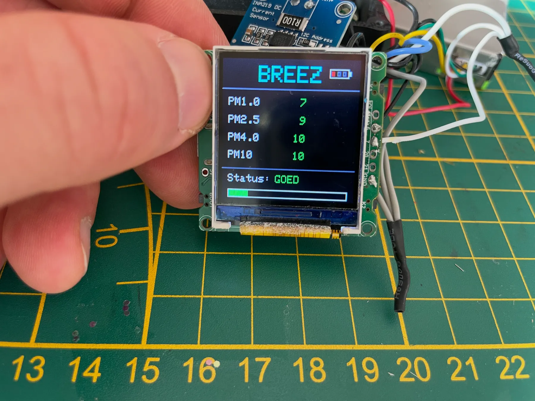
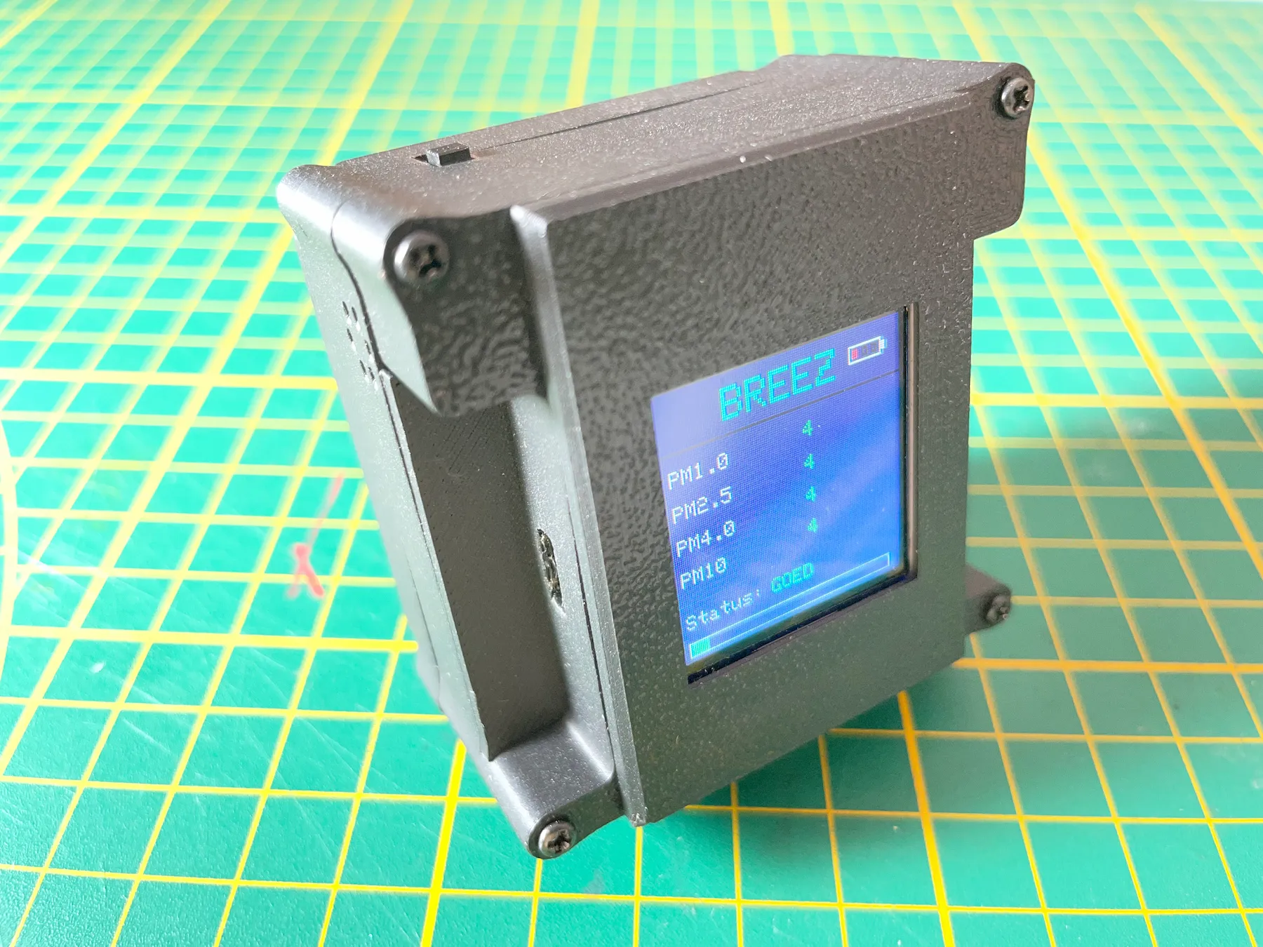
The BREEZ dust sensor and web environment are designed within the Capturing Dust community to make prototyping and research with particle sensors accessible for makers.
To build your BREEZ dust sensor you’ll need the Capturing Dust firmware and 3D print files. The sensor uses off-the-shelf electronics, keeping the project accessible for the community.
The BREEZ dust sensor can work as a stand-alone sensor. The BREEZ platform adds information, insights, live views and history. Access to the BREEZ platform comes with a Capturing Dust Patreon subscription.
Free guide. Supporter files.
This guide walks through the complete process for free. Firmware, 3D print files and BREEZ platform access are available through Capturing Dust Patreon.
The sensor is designed to be self-built. This is a challenging project that requires patience, soldering and basic 3D printing experience. If you are new to either, this project is also a good opportunity to learn along the way.
ComponentsTools
Materials
Prepare the parts before you solder.
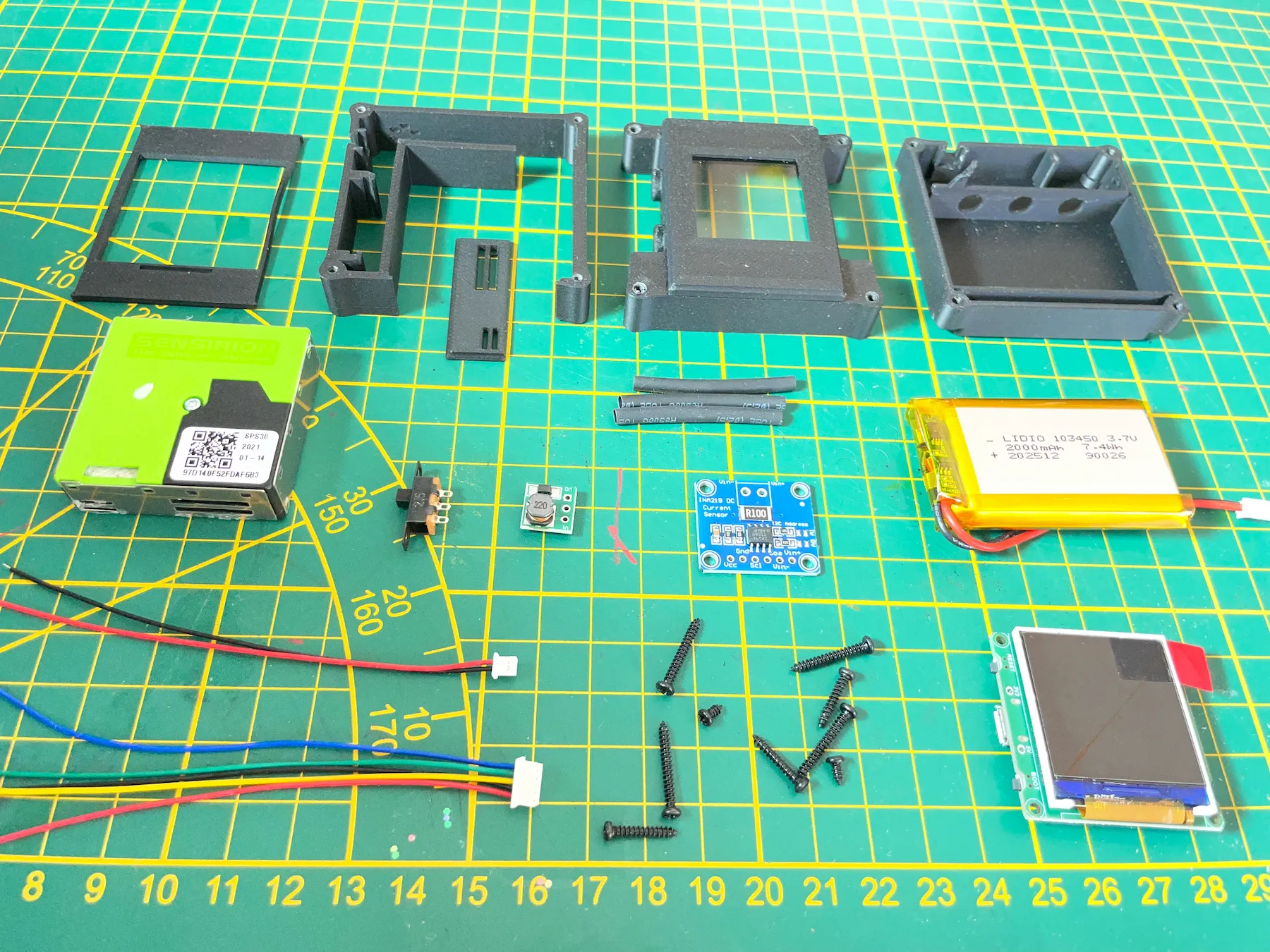
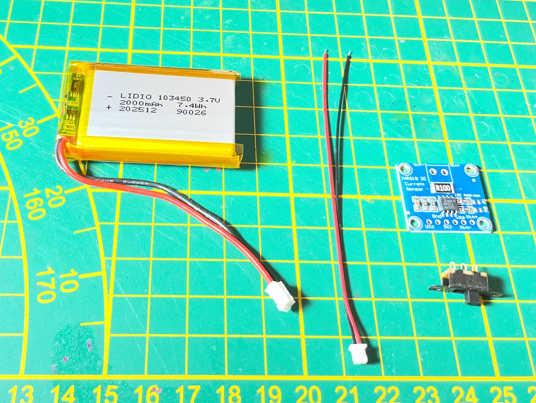
Required components
Spotpear ESP32-C3 Trinket Mini TV
INA219 module
0.9–5V step-up power module
30 AWG flexible silicone wire
Heat shrink tubing in various diameters
Sensirion SPS30 sensor
6 mm slide switch SS12F15
2000 mAh 3.7V battery, 103450 — 50×34×10 mm
Micro JST 1.25 2-pin male connectors
1 mm polycarbonate or acrylic sheet
1 mm double-sided foam tape, 3 mm width
4× M2×12, 4× M2×16 and 4× M2×5 self-tapping screws
Print settings
Layer height: 0.08 mm
Nozzle size: 0.4 mm
Wall loops: 4
Supports: automatic tree, 15 degrees
Estimated cost
Approximately €50–70 in materials, depending mainly on the local price of the SPS30 sensor.
Wiring diagram
Dry fit before soldering.
The sensor uses off-the-shelf electronics. This keeps the project accessible, but also makes the wiring and soldering fairly compact inside the enclosure.
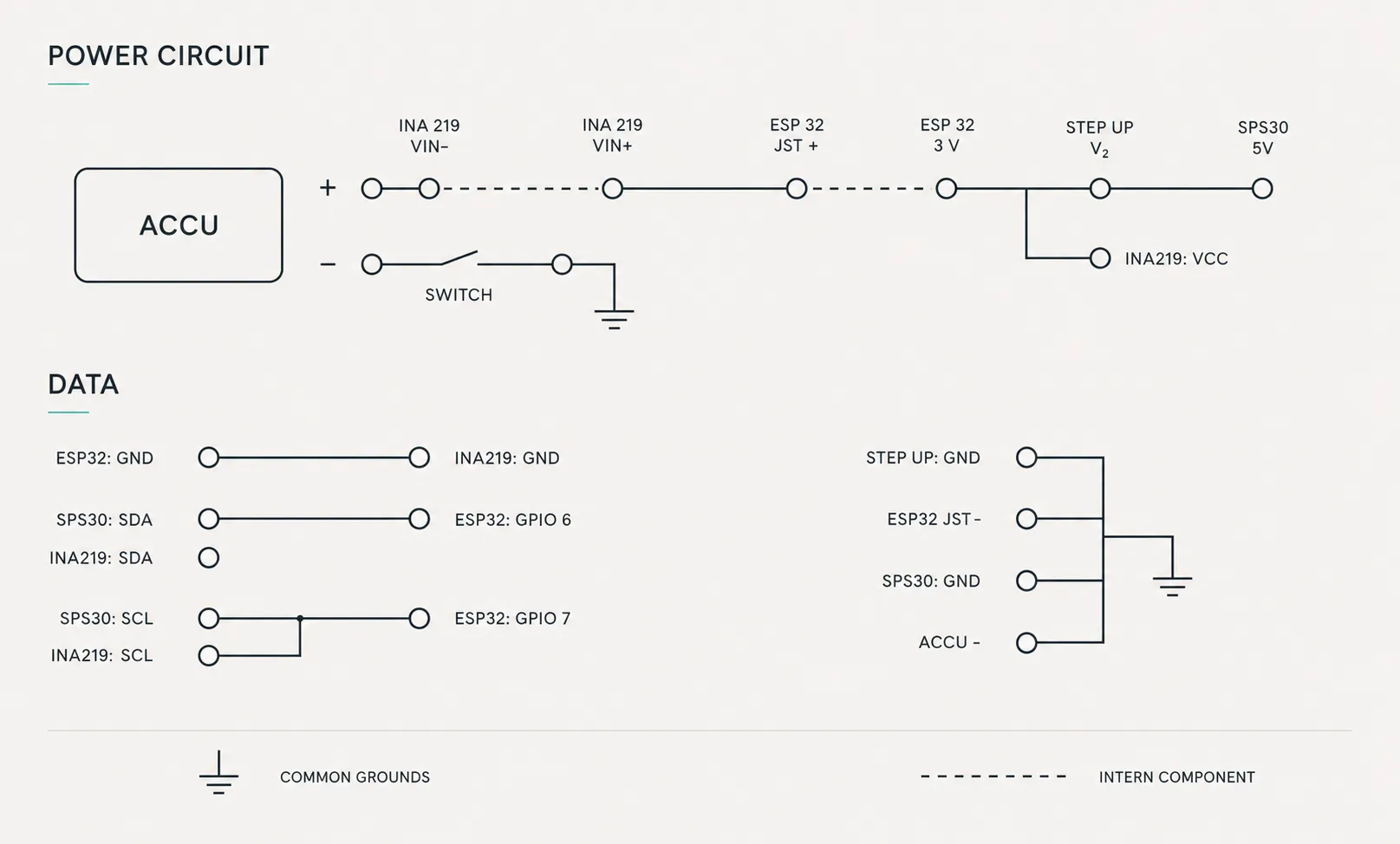
Before soldering, place the components into the enclosure first and study how the wires will be routed. The wiring overview below shows how the circuit should be connected.
Assembly
Solder the power circuit.
Plan the power path
The ESP32 uses a JST 1.25 connector. Many batteries do not include the correct connector by default. Cable management is the real challenge, so dry fit all components in the 3D printed housing to understand cable lengths and routing.
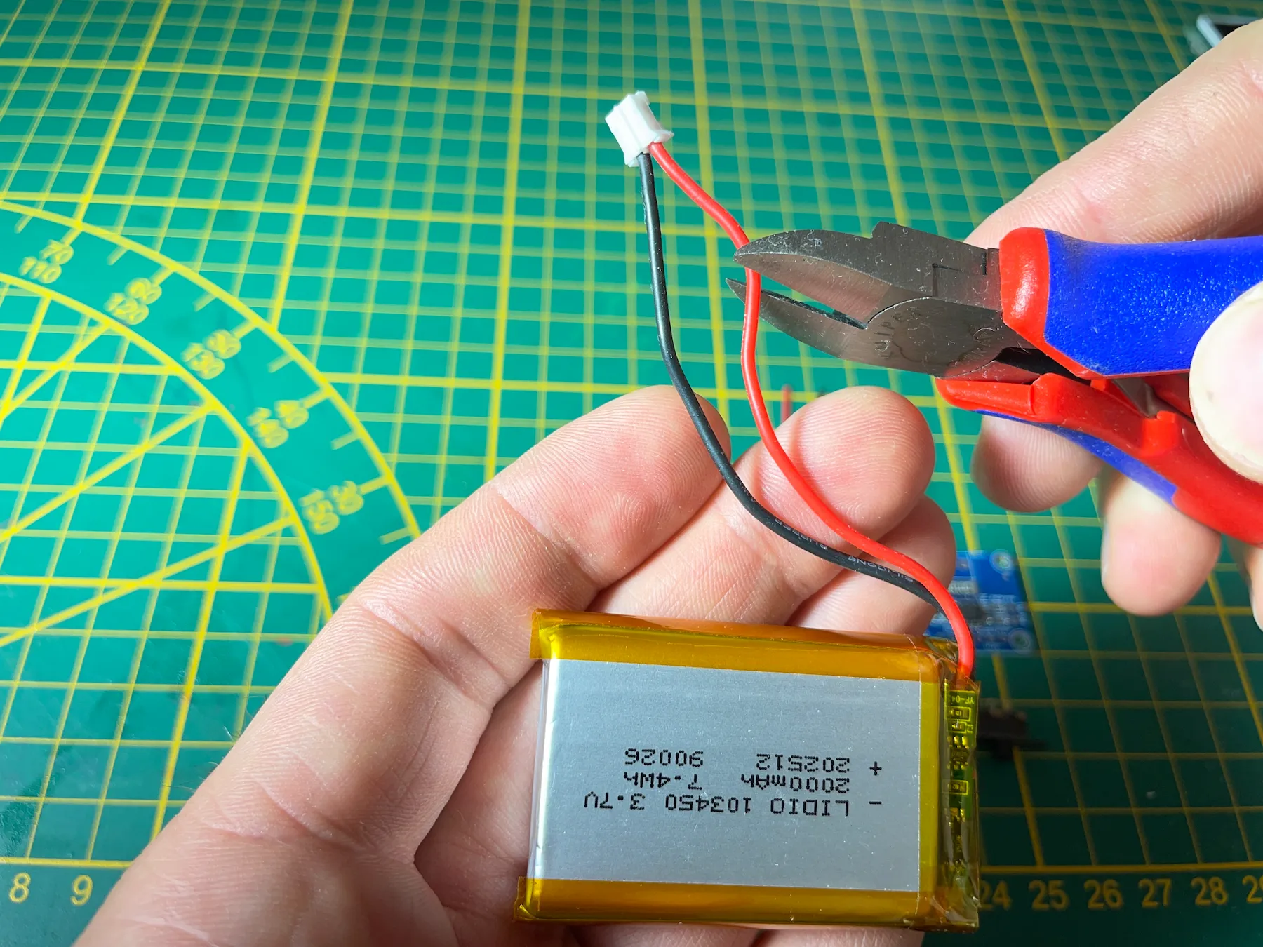
Cut one battery wire at a time
To connect the battery with the JST 1.25 connector, first cut the standard connector from the battery. Do not cut both battery wires at one time because this will cause a short circuit.
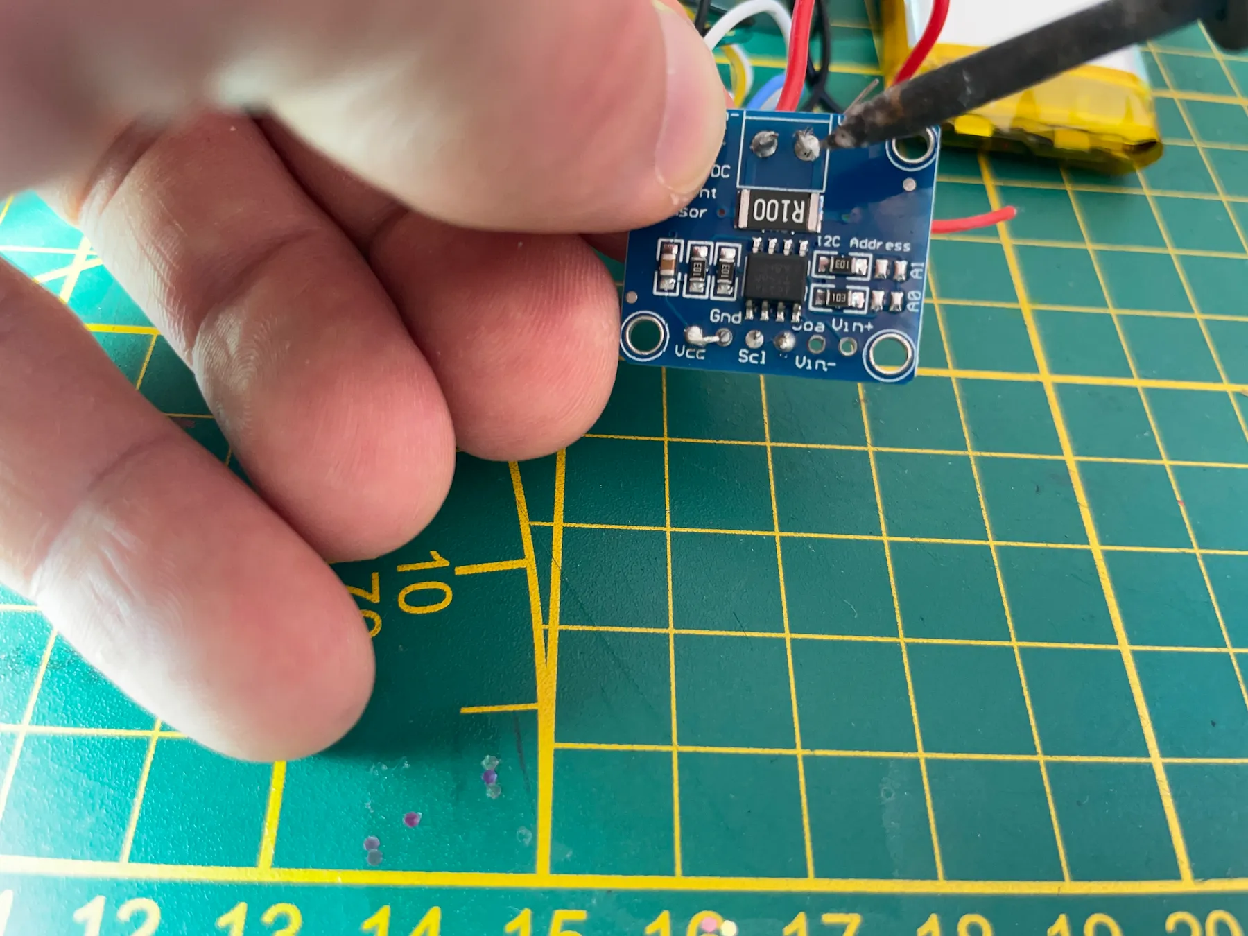
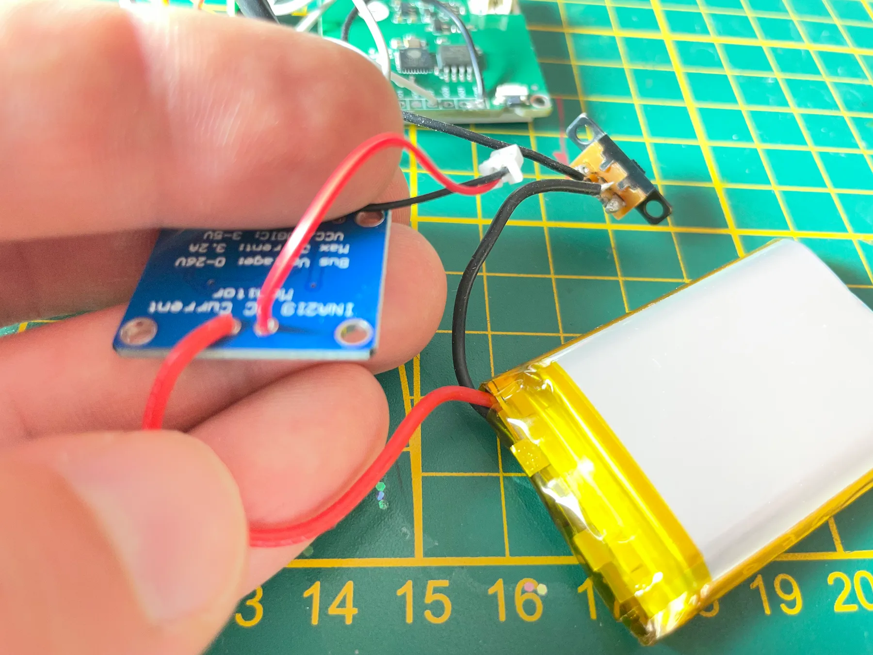
Solder INA219 and the switch
Connect the INA219 and the switch to the battery according to the power circuit. Pay close attention to wire direction while soldering. On all circuit boards, wires should exit from the back side of the board to avoid assembly problems later.
Complete the battery circuit
Solder the JST 1.25 connector to the INA219 board. This completes the main power supply for the ESP32.
Please note for later use: The battery will only charge when the power switch is turned ON.
Split power for the SPS30
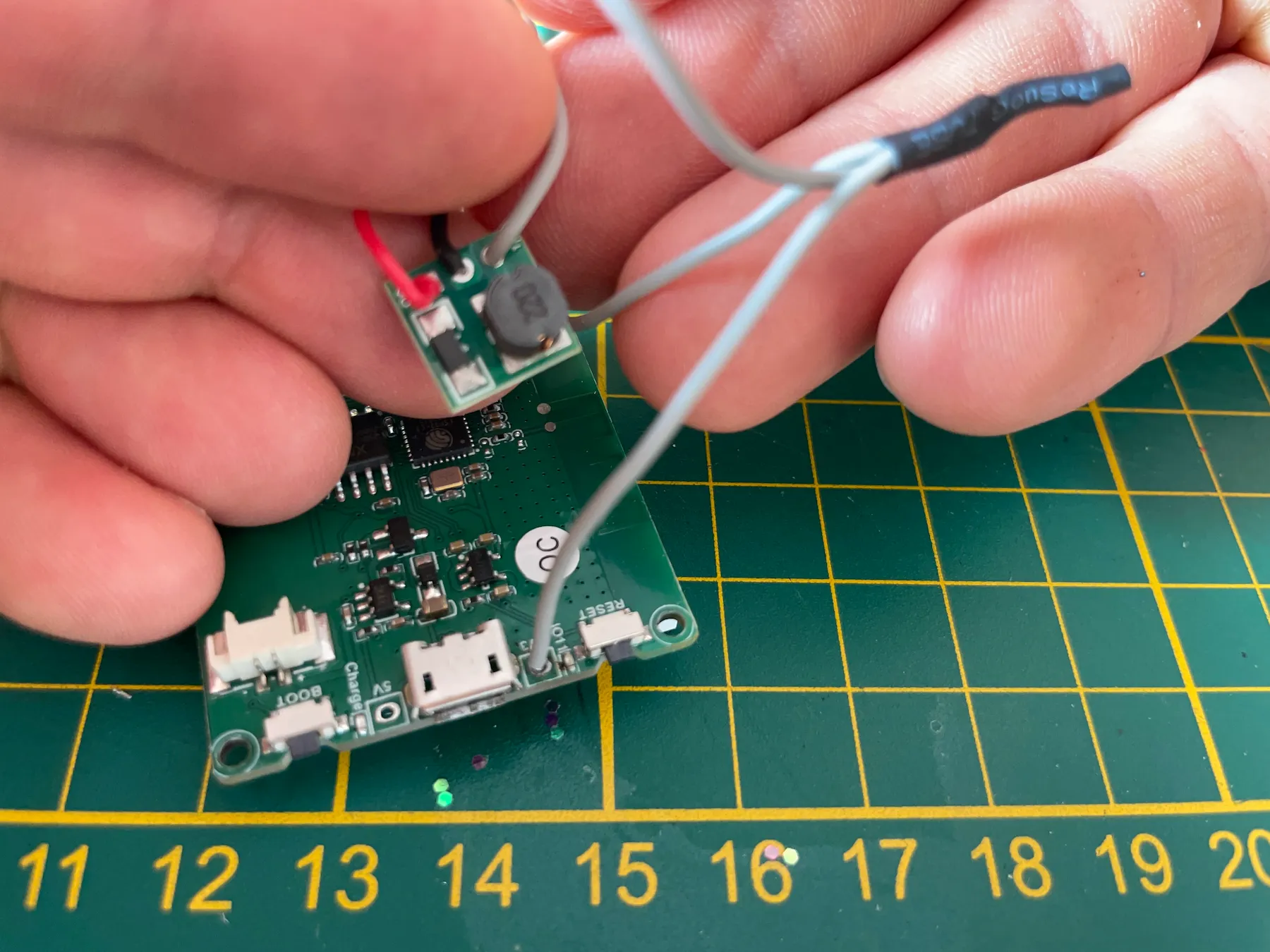
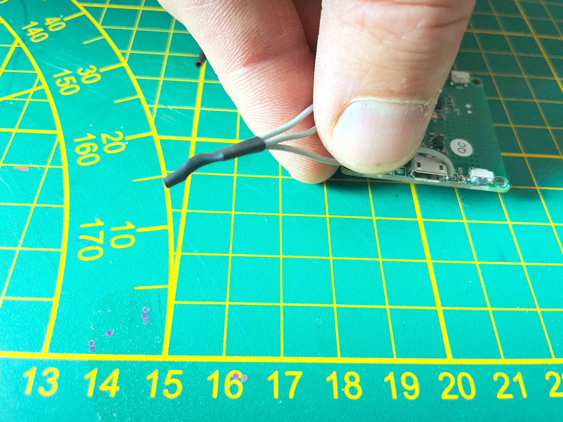
The SPS30 sensor needs 5 V input. Use the 3 V outlet GPIO on the ESP32 next to the USB connector, then route from this 3 V point to the step-up board and the INA219 VCC connector. Solder three wires to make the split and cover it with heat shrink tubing.
Combine wires cleanly
When combining multiple wires, strip the wires, twist them together, solder them and cover the joint with heat shrink tubing.
Strengthen delicate sensor wiring
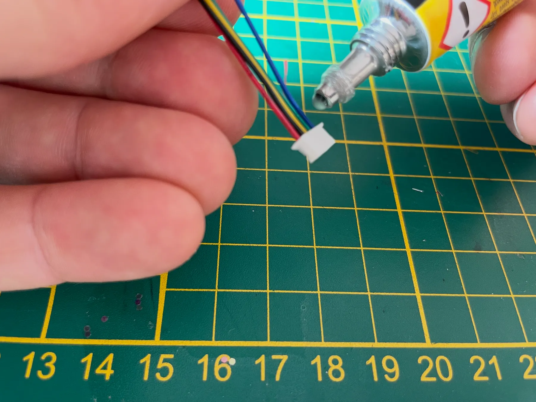
The connector for the SPS30 can have a delicate connection. Add repair gel for extra strength, then follow the wiring instructions to finish soldering the project.
Firmware
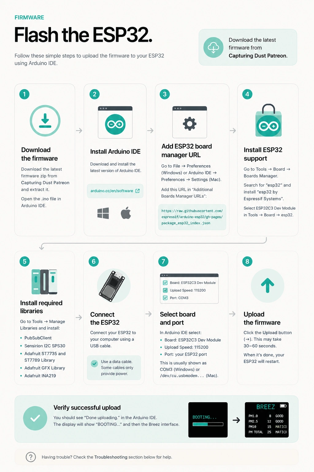
Flash the ESP32.
Upload the BREEZ firmware after soldering, before the ESP32 becomes harder to reach inside the housing.
The firmware package and 3D print files are available through Capturing Dust Patreon. The full visual flashing guide is linked here so this page can stay clean and focused.
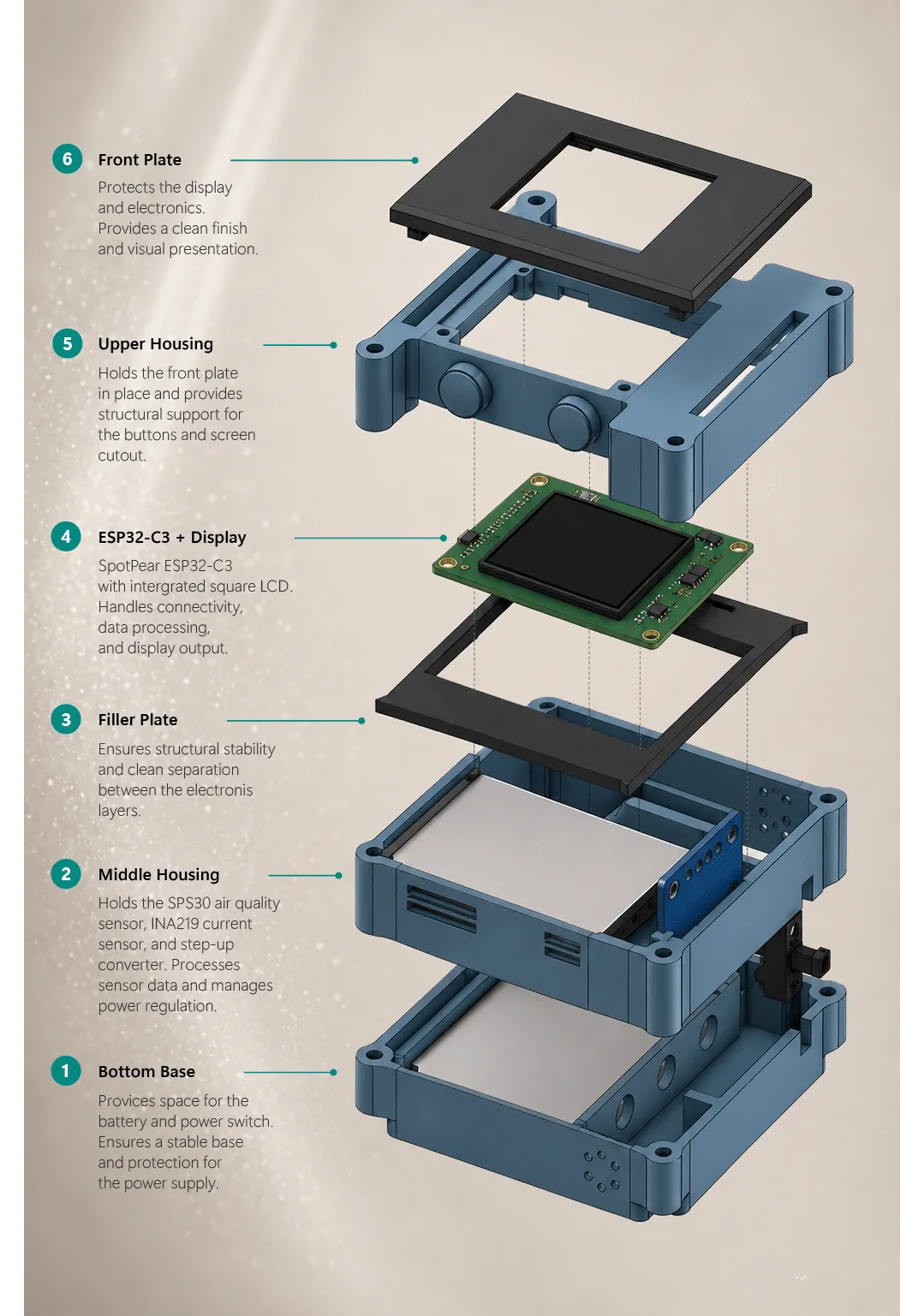
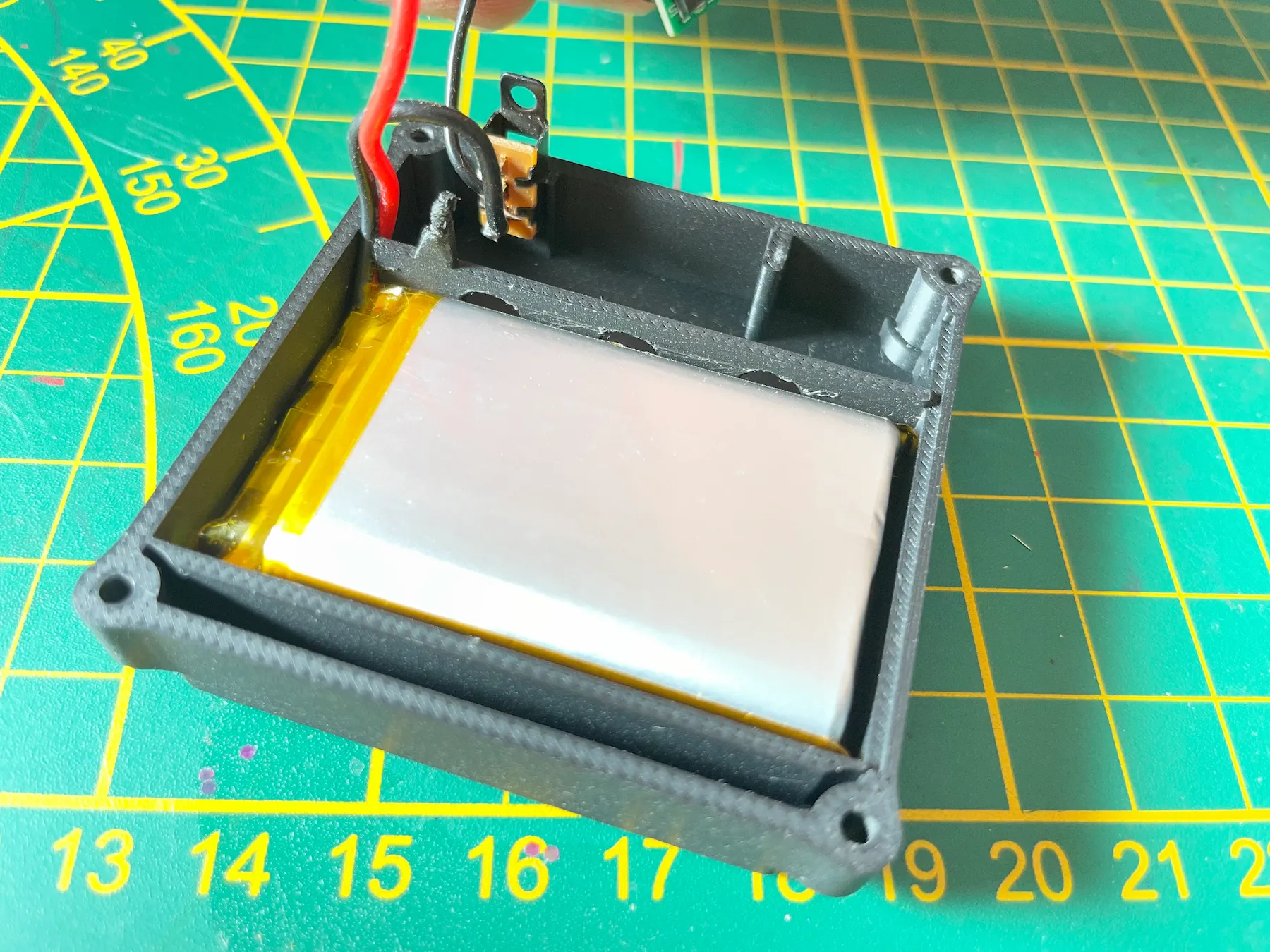
Once soldering is ready, place the components in the housing. Start with the battery and switch in the bottom housing.
middle housing
Stack the housing and organize the cables.
Place the middle housing
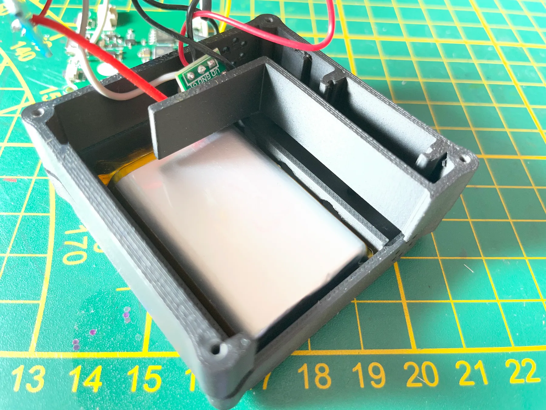
Place the middle housing on top of the bottom housing. Make sure all cables sit in the compartment on the back.
Screw the lower sections together
Screw the bottom to the middle housing for easier assembly of the rest of the build.
Slide in the INA219
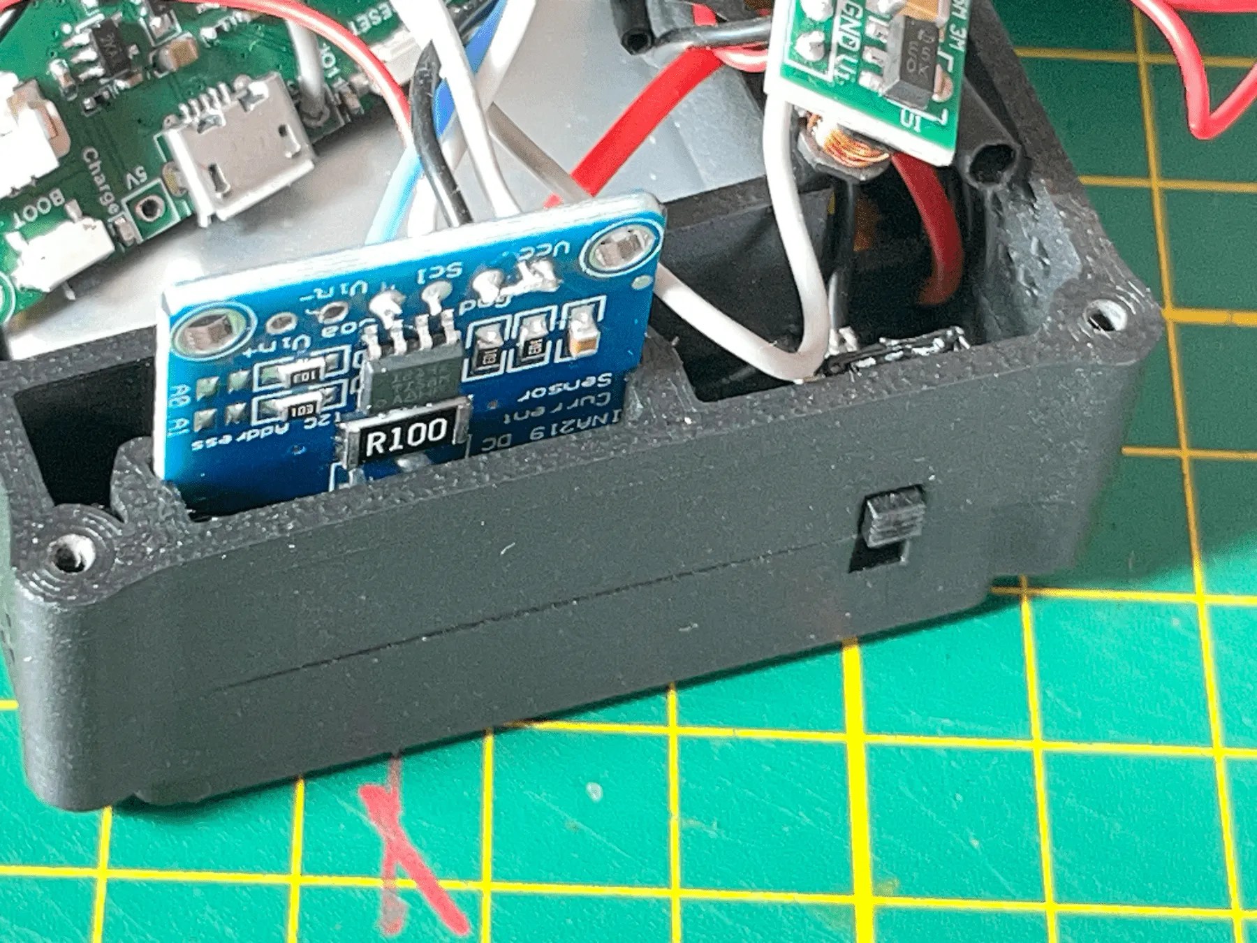
Slide the INA219 into the board slots as shown. Slide it downward until it rests against the stop block.
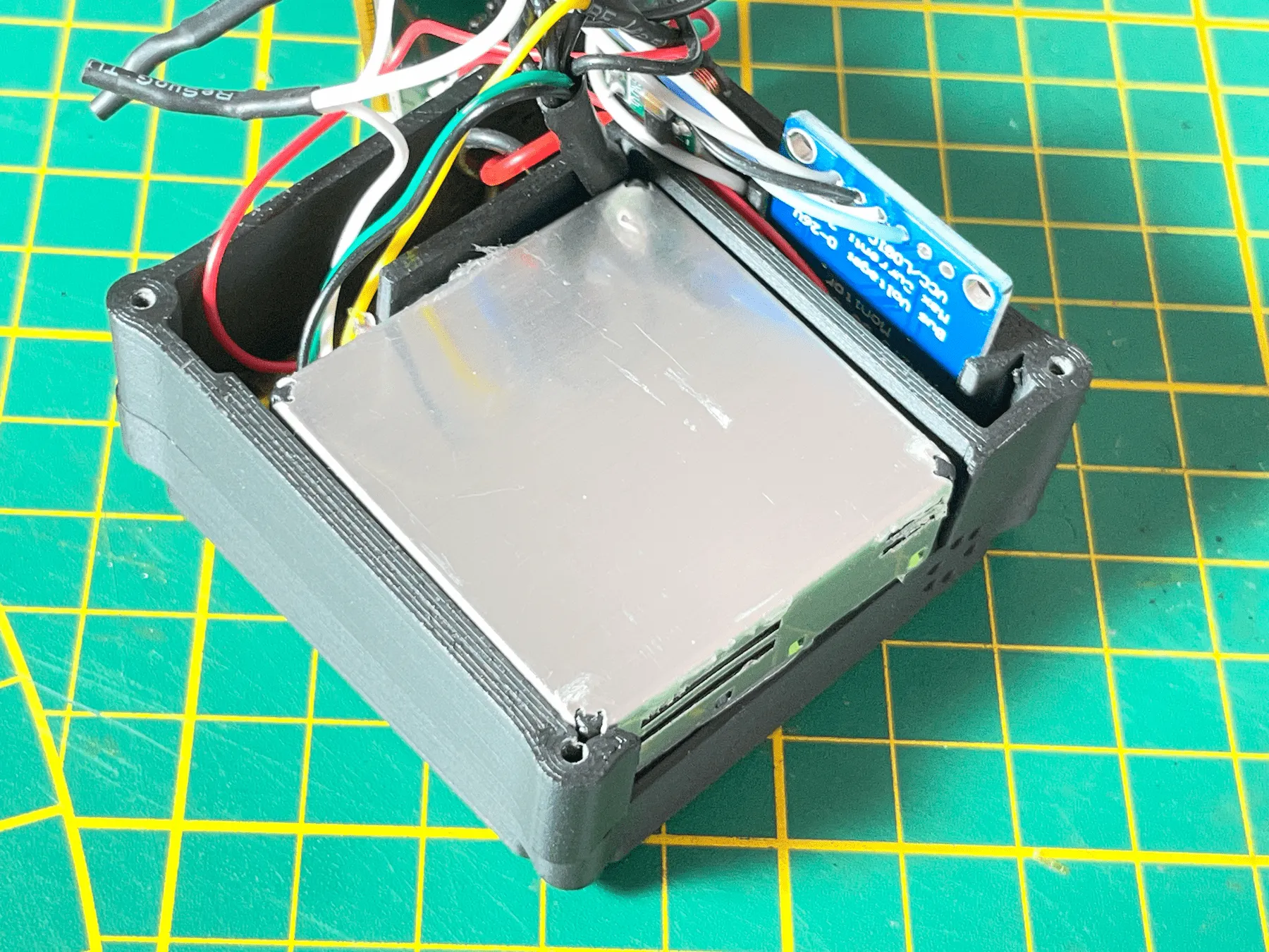
Place the sensor
Place the sensor in the middle housing with the green side facing downwards. Keep an eye on cable management. If wires are too short or too long, fix them now.
Top section
Build the display and close the housing.
Prepare the display window
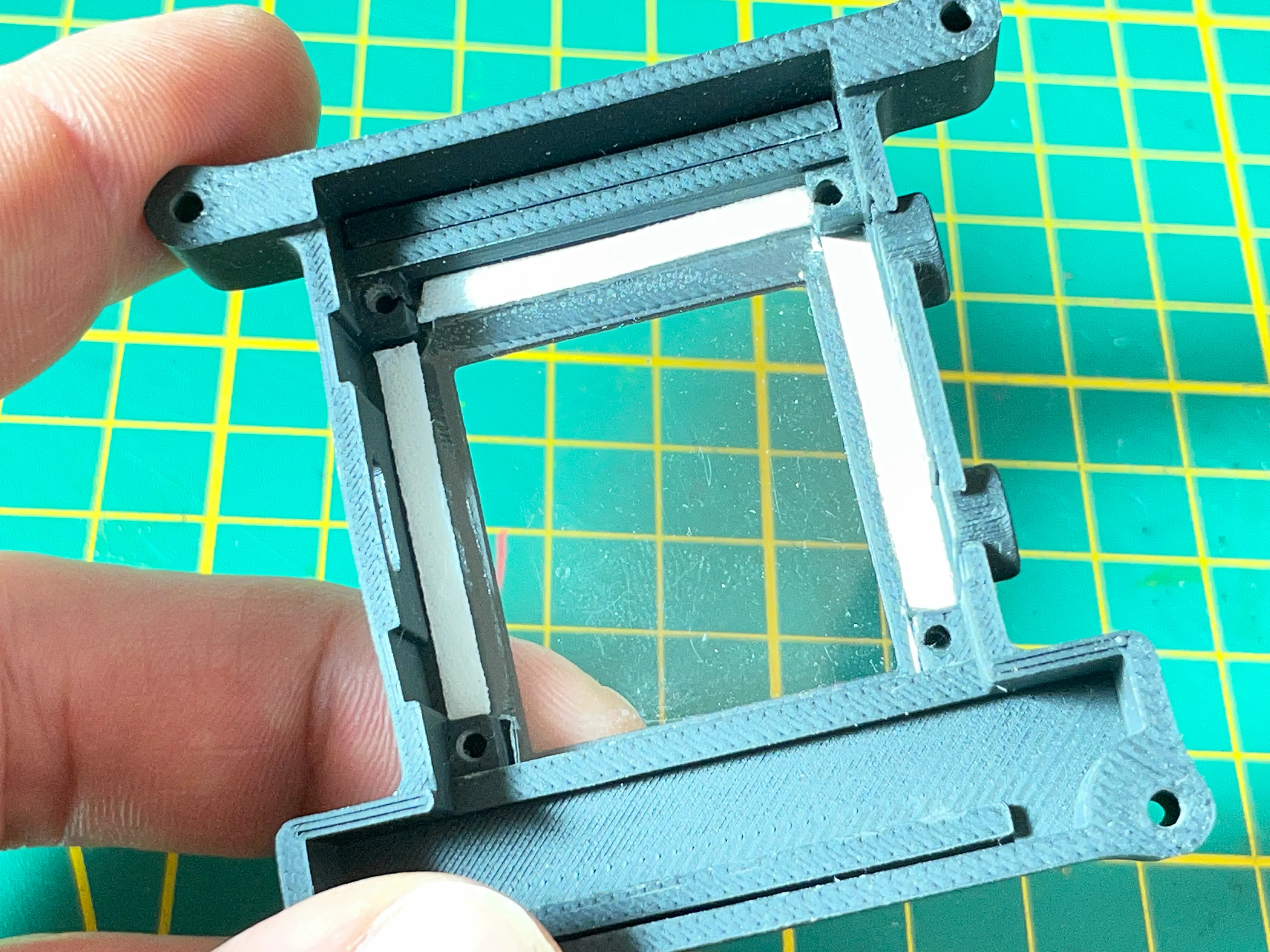
Cut a piece of 1 mm polycarbonate or acrylic to approximately 29.8 mm × 39 mm. Score the plastic with a sharp knife and straight edge, repeat several passes and gently snap along the scored line. Mount the acrylic to the inside of the front plate with thin double-sided tape, snap the front plate into the upper housing and add 1 mm double-sided foam tape at the sides to absorb shocks on the ESP32.
Feed the ESP32 through the filler plate
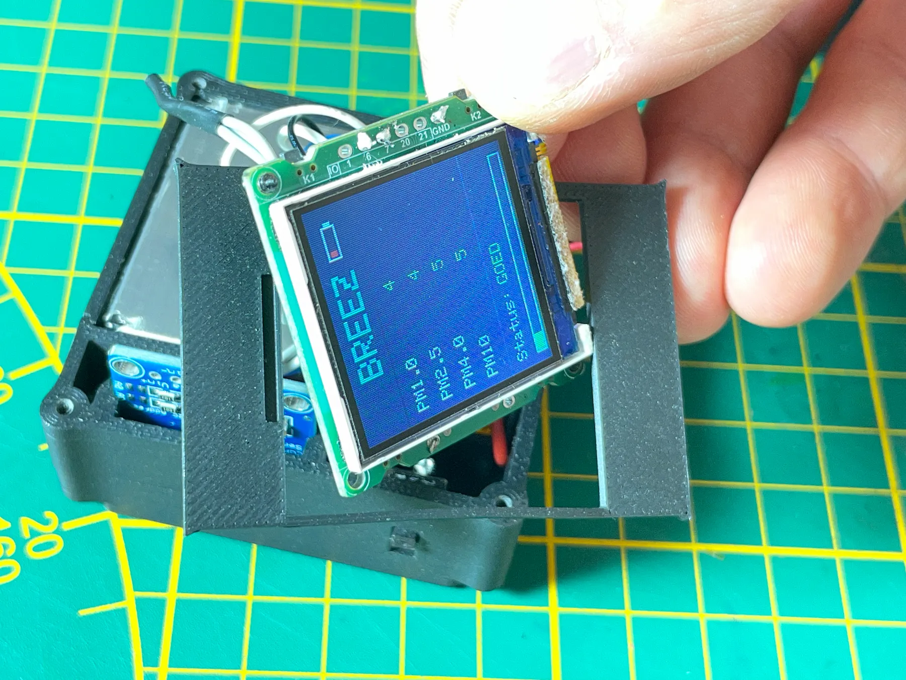
Before the ESP32 can be put into place, take the ESP32 through the filler plate. Make sure the slot in the plate and the symbols are in the same direction as the screen.
Screw the ESP32 into the housing
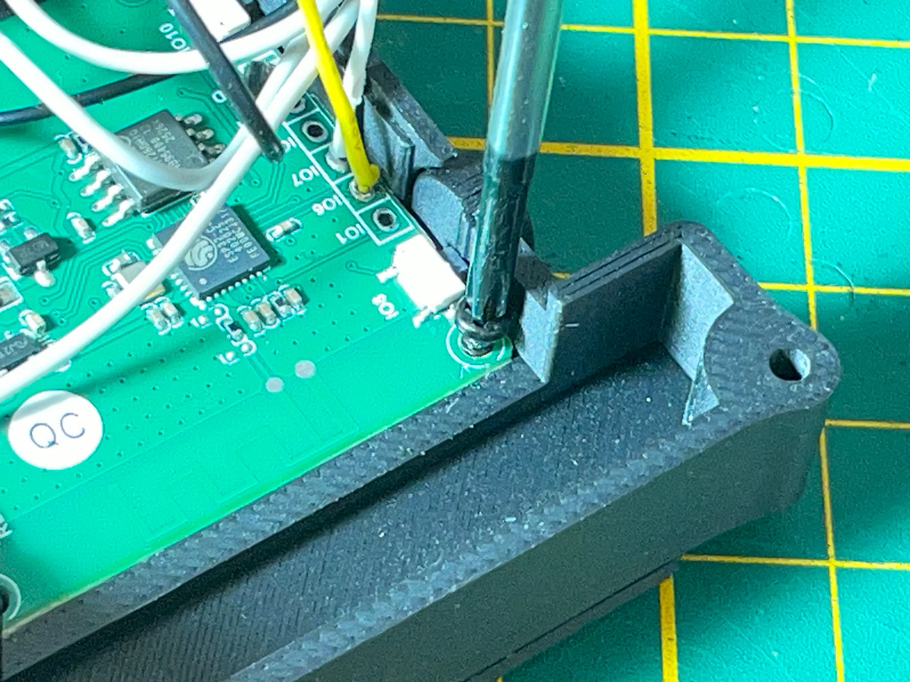
Place the ESP32 in the housing. Start with the USB connector in the slot, then push the opposite side of the board in. Be careful not to damage the board buttons. Use 4× M2×5 self-tapping screws to mount the board.
Secure the step-up board
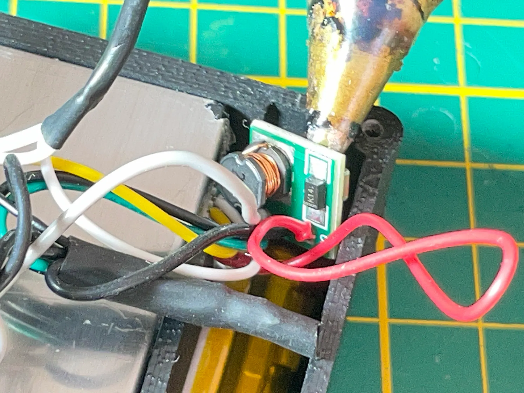
Use hot glue to place the step-up board against the wall of the housing so all sensor parts are secured firmly. Electronics-safe double-sided tape can also help.
Snap the filler plate into place
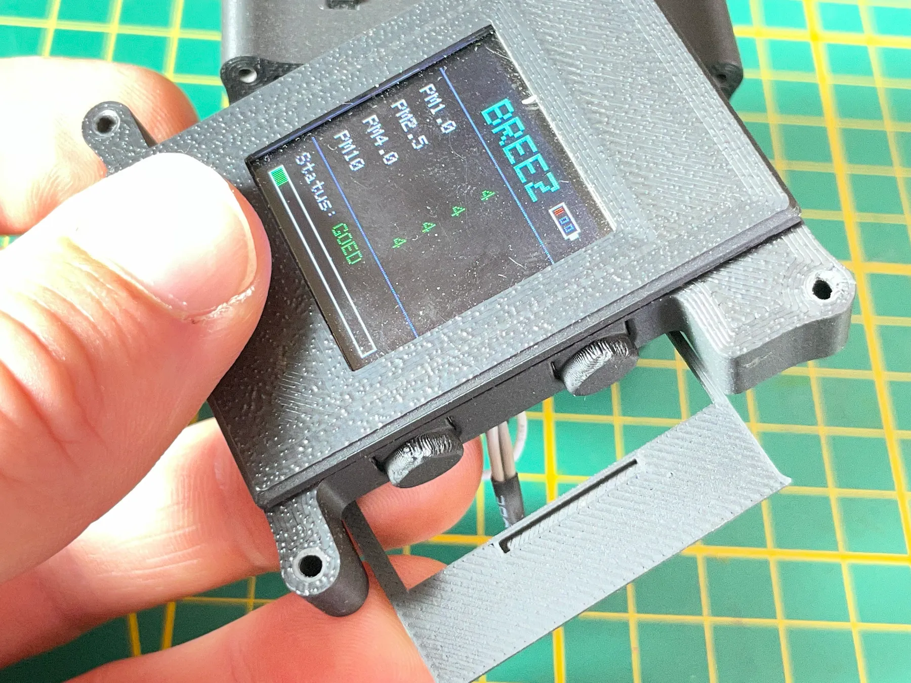
Now the ESP32 is screwed onto the top section, snap the filler plate into place.
Place the air vent
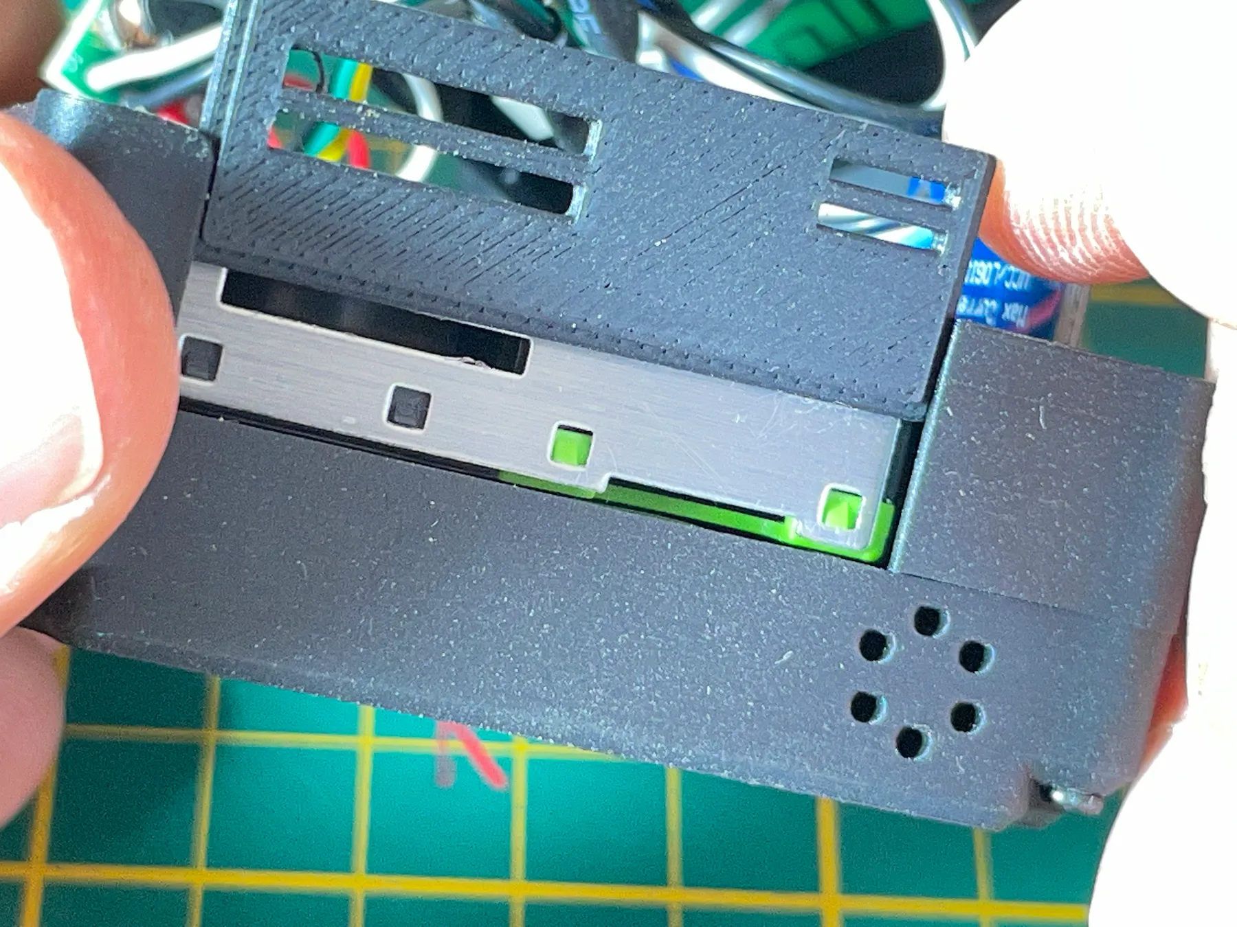
Place the air vent into the middle housing.
Test before tightening
Before fully tightening the enclosure, test the device once more and verify the display and sensor still operate correctly. If the device no longer powers on, check whether a solder joint came loose during assembly.
Close the enclosure
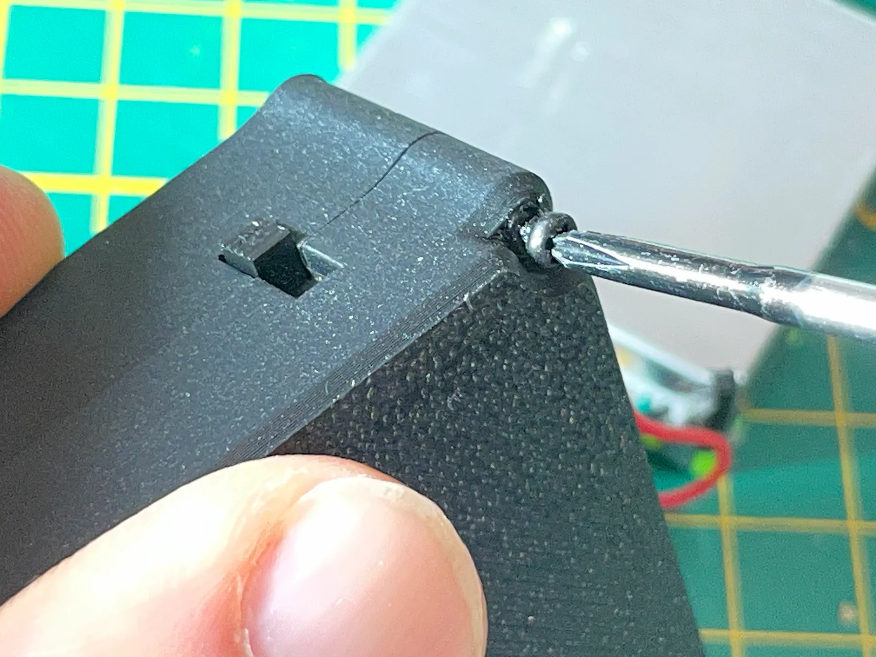
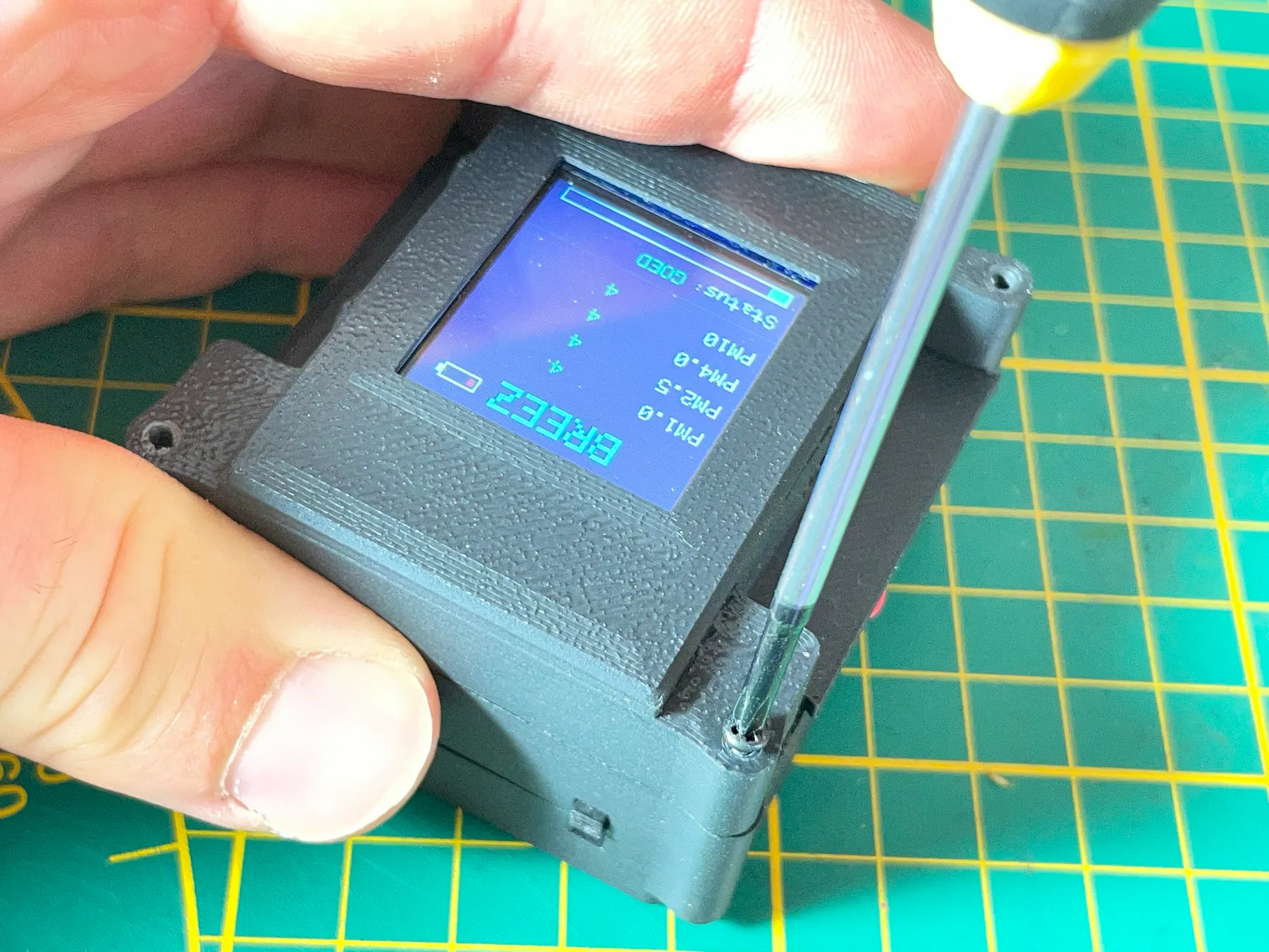
With the remaining long screws, screw the front section of the housing onto the middle housing. Carefully guide wiring into the enclosure while closing it. Wires should not be pinched or under tension. A small screwdriver can gently push wires into place.
You did a thing
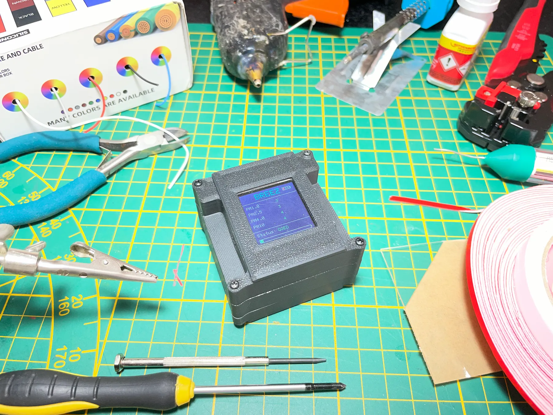
You’ve finished the build on your BREEZ dust sensor.
Open for makers
You built a fully operational portable dust sensor.
If you are a developer and want to write your own firmware, that’s completely possible. The sensor can also be used independently from the web platform, and you are free to modify the hardware or software for personal, non-commercial use.
Got questions? Read our FAQ for quick help, or join the Capturing Dust Patreon community for priority support.