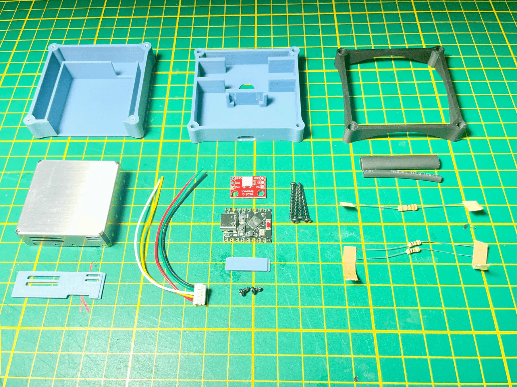
Required components
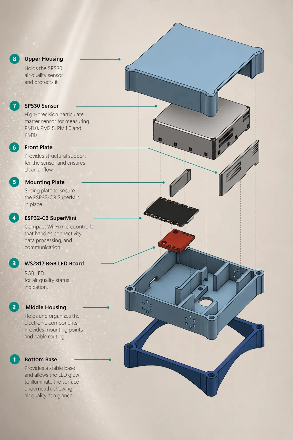
- ESP32-C3 SuperMini
- WS2812 RGB LED board
- Sensirion SPS30 particulate matter sensor
- 30 AWG flexible silicone wire
- Heat shrink tubing
- 4 × M2 × 16 self-tapping screws
- 2 × M2 × 5 self-tapping screws
Public maker guide
The BREEZ SuperMini is a simpler dust sensor build using an ESP32-C3 SuperMini, a Sensirion SPS30 and RGB LED glow. Fewer parts, no screen and no battery circuit — made for makers who want a cleaner first build.
Get started
The sensor is designed to be built by you. Whether this is your first soldering project or you've built electronics before, take your time. This project is a great introduction to soldering, 3D printing and flashing firmware. The build is very straightforward, and nothing you can't do.
Materials
These settings worked well during development.
Approximately €20–30, depending mainly on the local price of the SPS30 sensor.
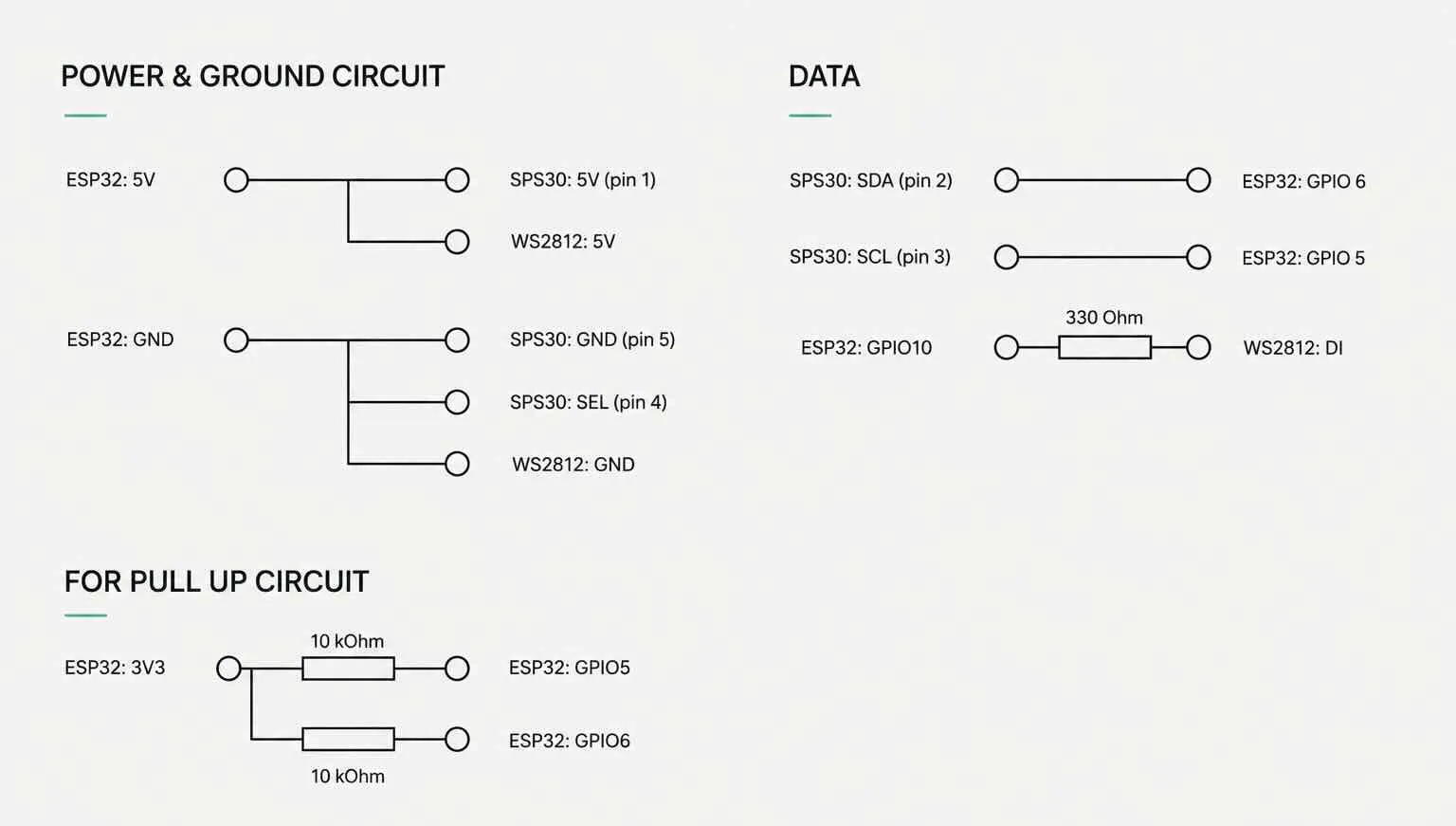
Wiring diagram
The BREEZ sensor uses standard off-the-shelf components. This keeps the project accessible.
Before soldering, place the components in the enclosure first. This helps determine the required wire lengths and makes cable routing much easier.
Use the wiring diagram below as your reference throughout the build.
Soldering
Good cable management is one of the trickiest parts of this project. Before soldering, do a complete dry fit of all components inside the enclosure. This gives you a good idea of wire lengths and where every cable should run.
Begin by placing the two 10 kΩ pull-up resistors to the back of the ESP32. Then place the SDA and SCL wires to the GPIO pins. Finally solder the components in place.
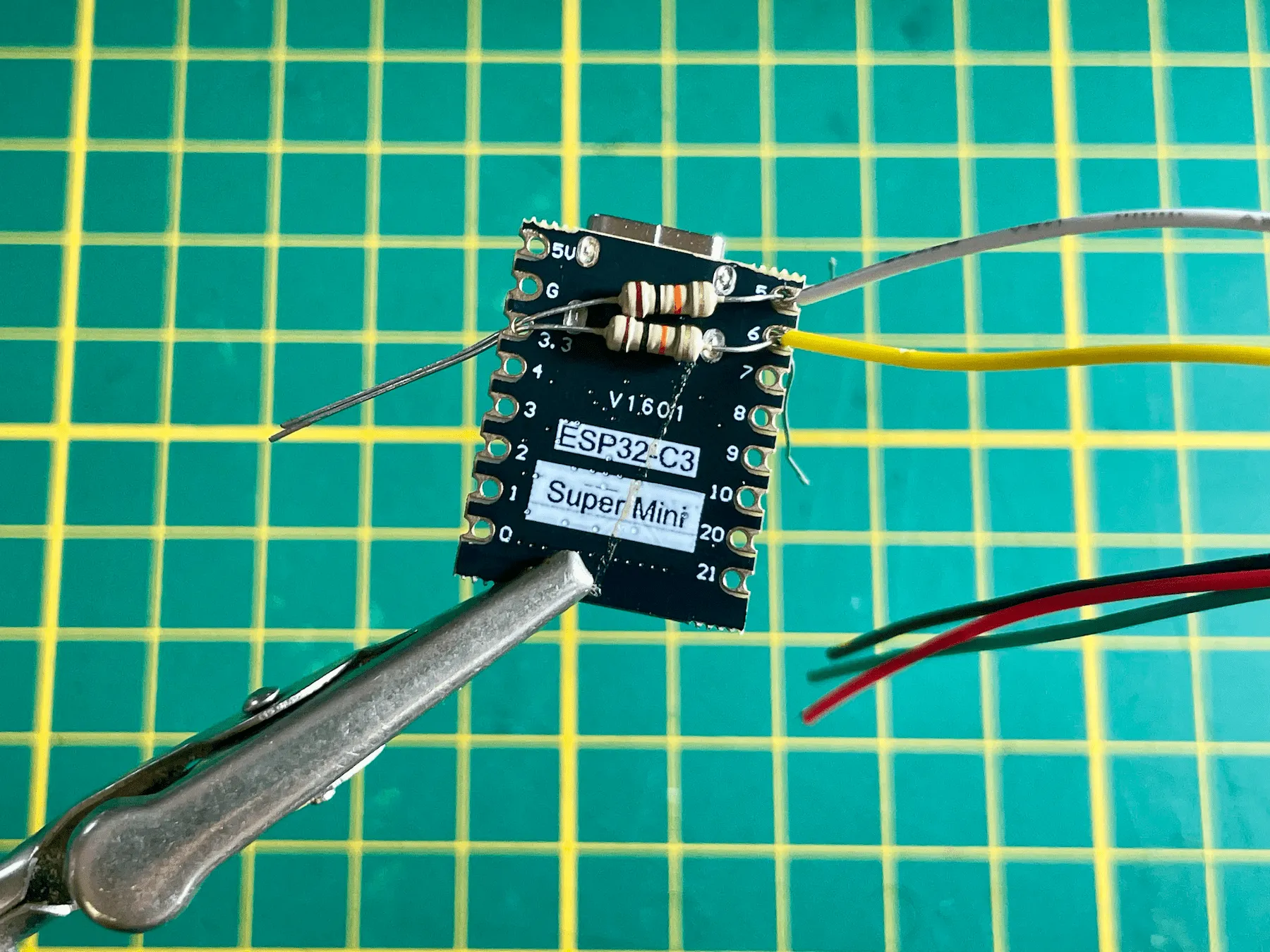
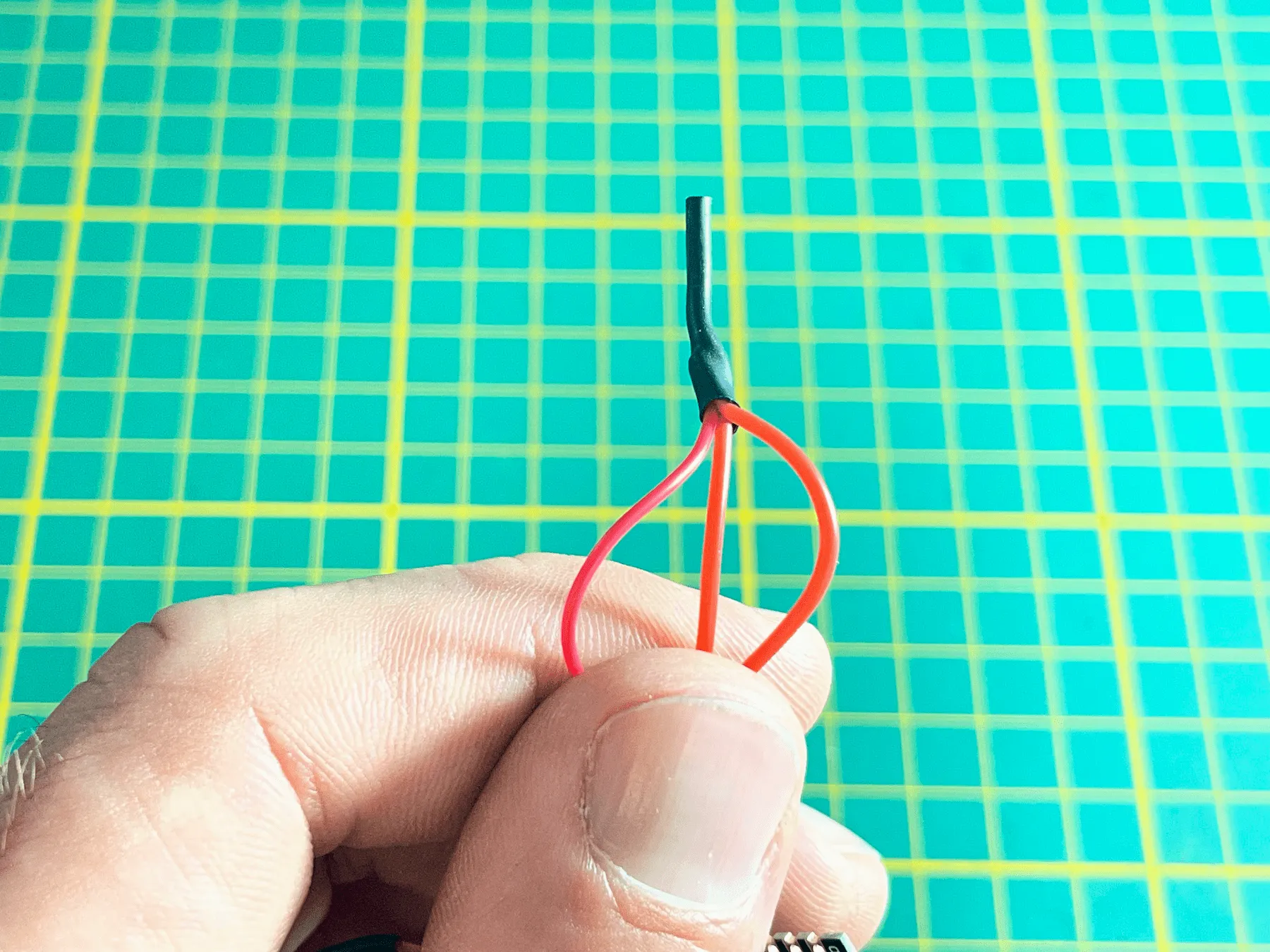
Both the SPS30 sensor and the WS2812 LED require 5 V. Create a small three-way connection from the ESP32 5 V pin to the WS2812 and the SPS30. Insulate the joint using heat shrink tubing.
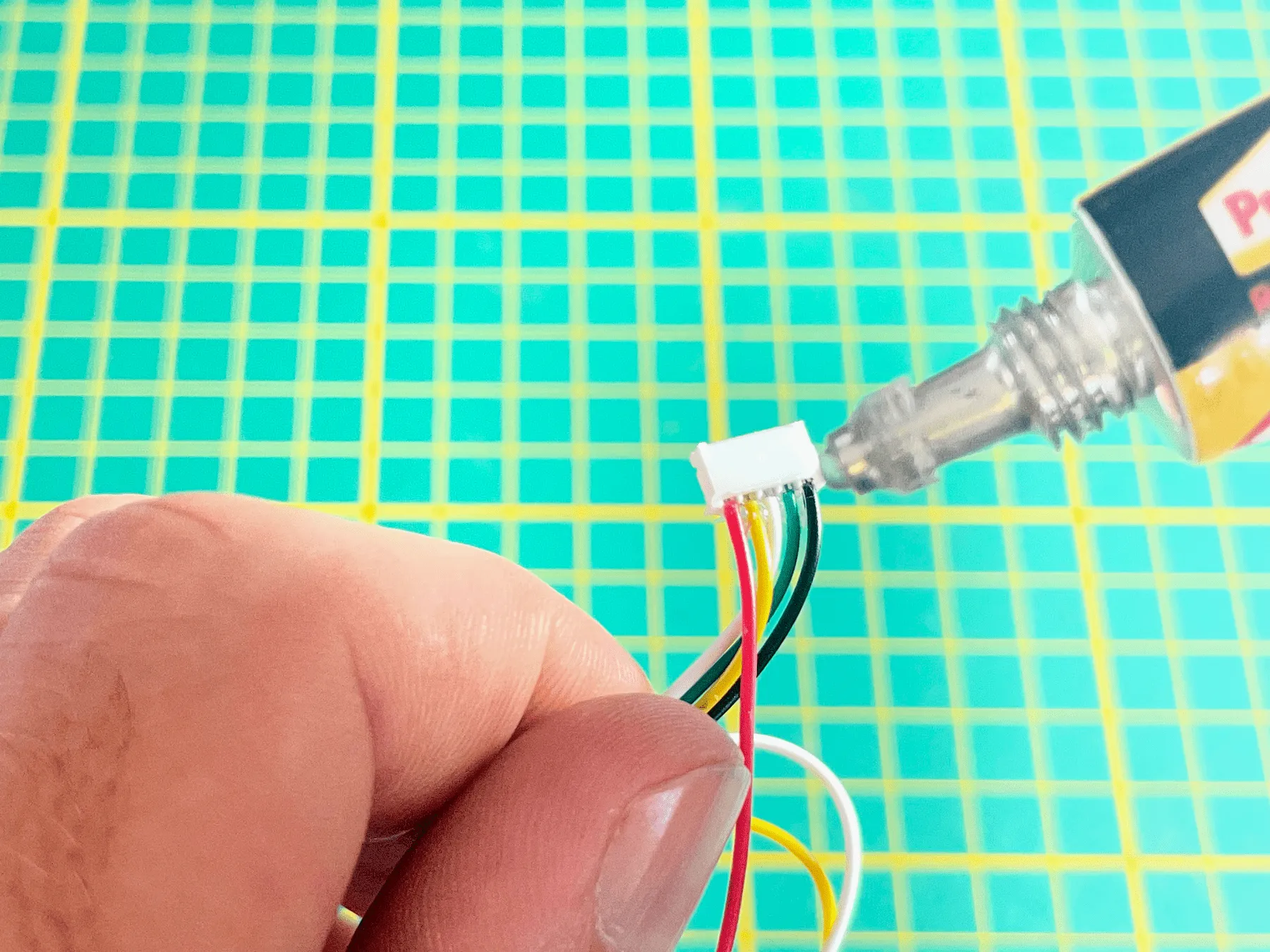
The connector on the SPS30 can be delicate. Adding a small amount of repair gel or flexible adhesive provides additional strain relief.
Continue soldering according to the wiring diagram. Wait to solder the 330-ohm resistor until you have screwed all the components into the casing.
Installing electronics
Once most of the soldering is finished, you can start installing the components.
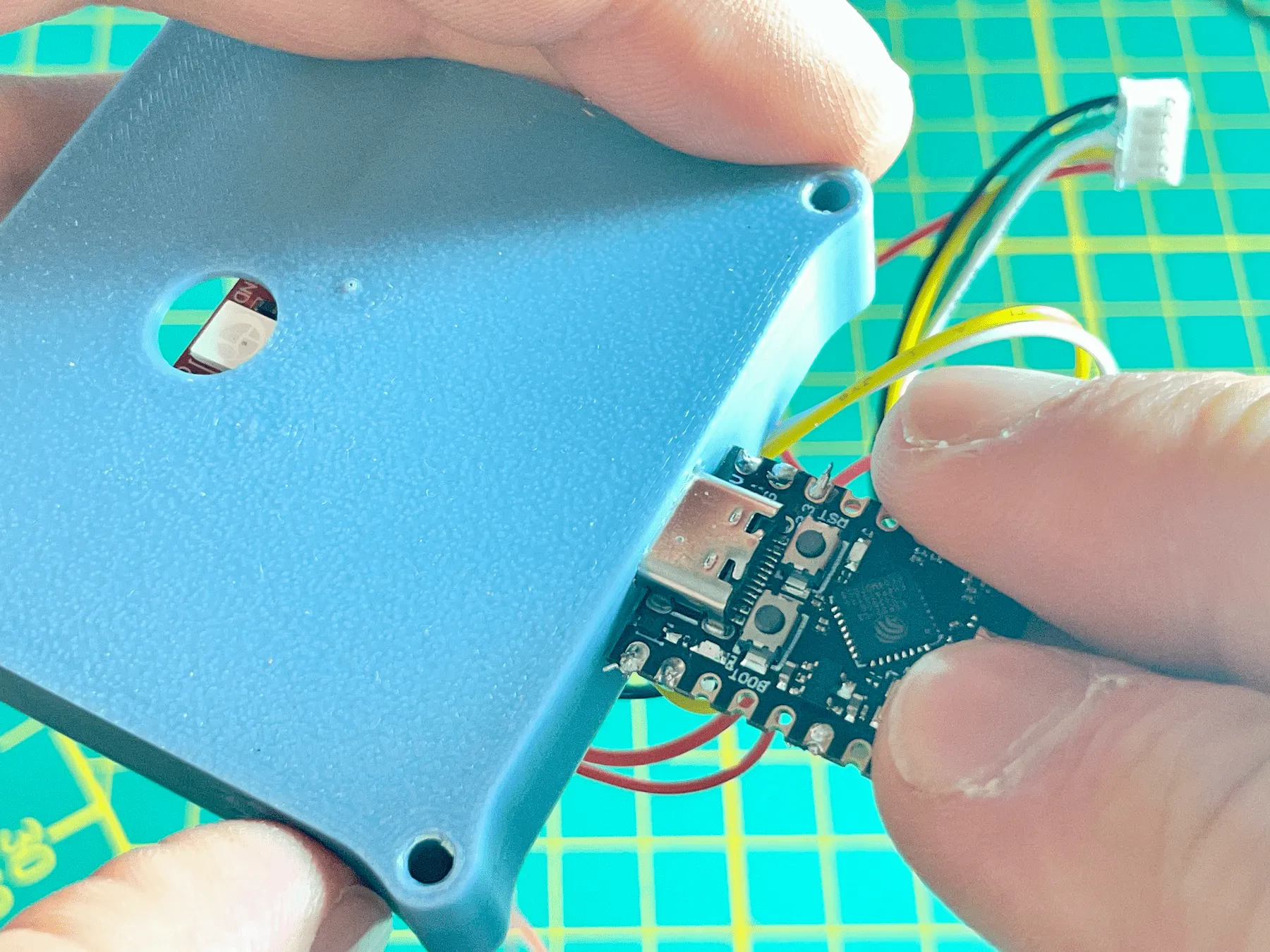
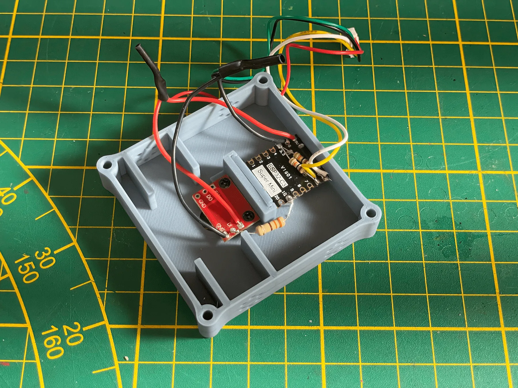
Begin with the ESP32. Carefully dry fit the USB connector from the outside into the opening in the enclosure to see how it fits straight from the 3D printer. Depending on your printer tolerances, you may need to remove a tiny amount of material with a hobby knife from the opening where the USB connector passes through.
The fit should be snug, but not forced. With a good fit, you can place the ESP32 into position. Slide the USB connector into the opening first, then push the back of the ESP32 downward. Then slide the ESP32 holder fully down into the slot.
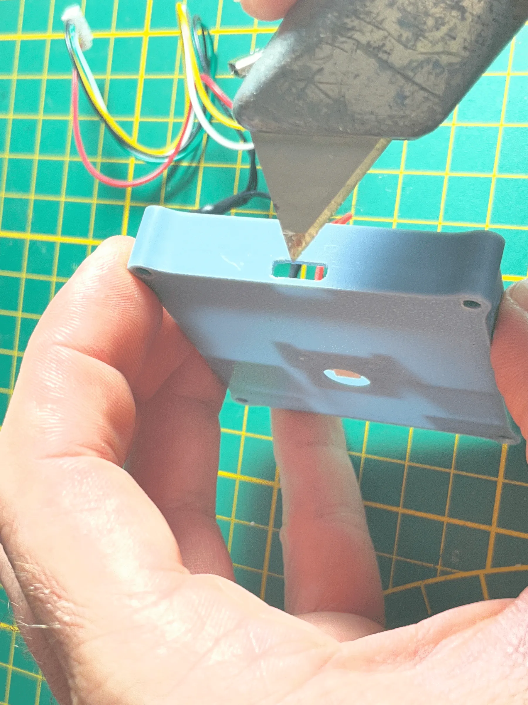
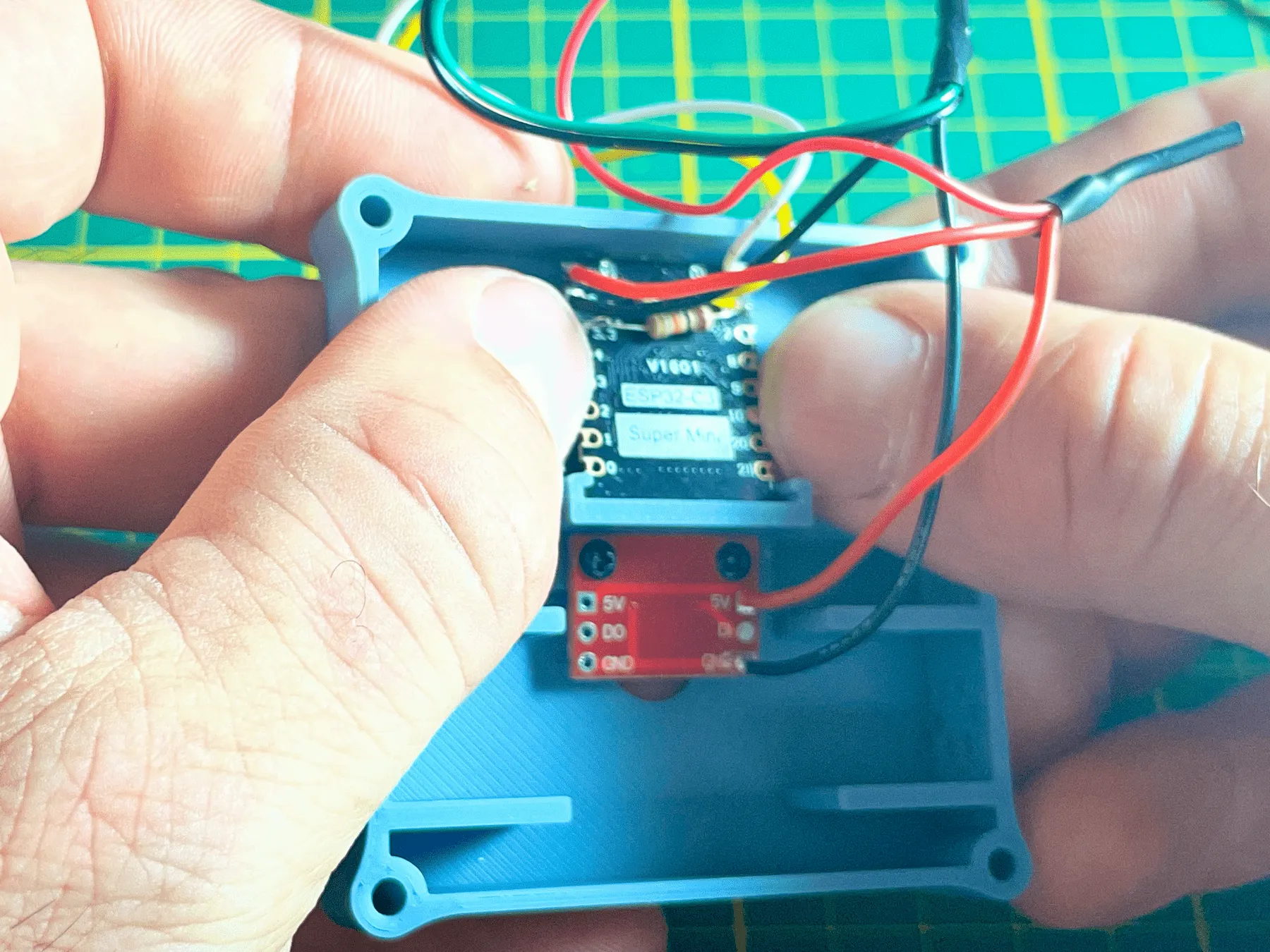
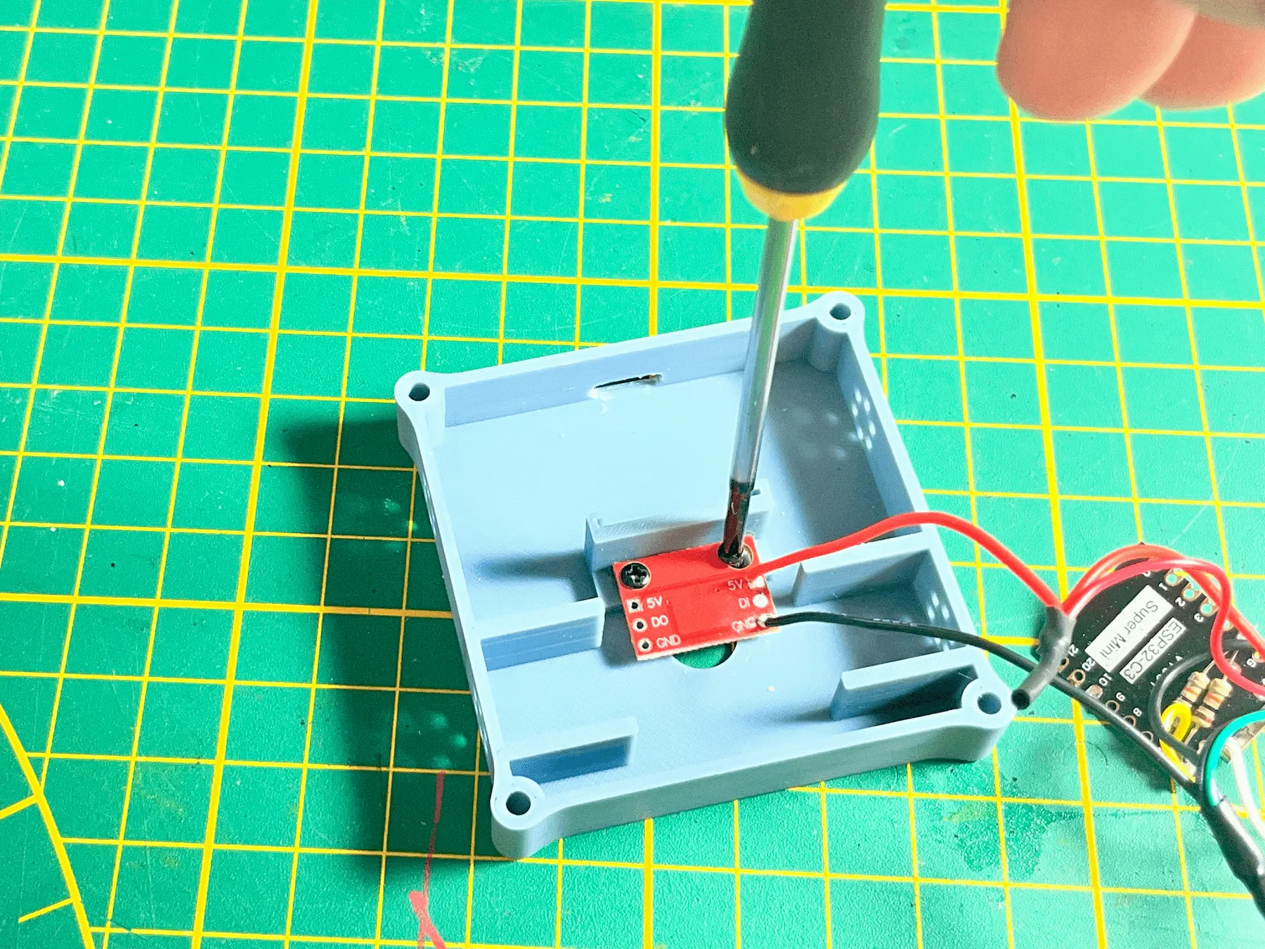
Next, mount the WS2812 LED board using the two short screws. Check that the LED is placed directly above the LED hole.
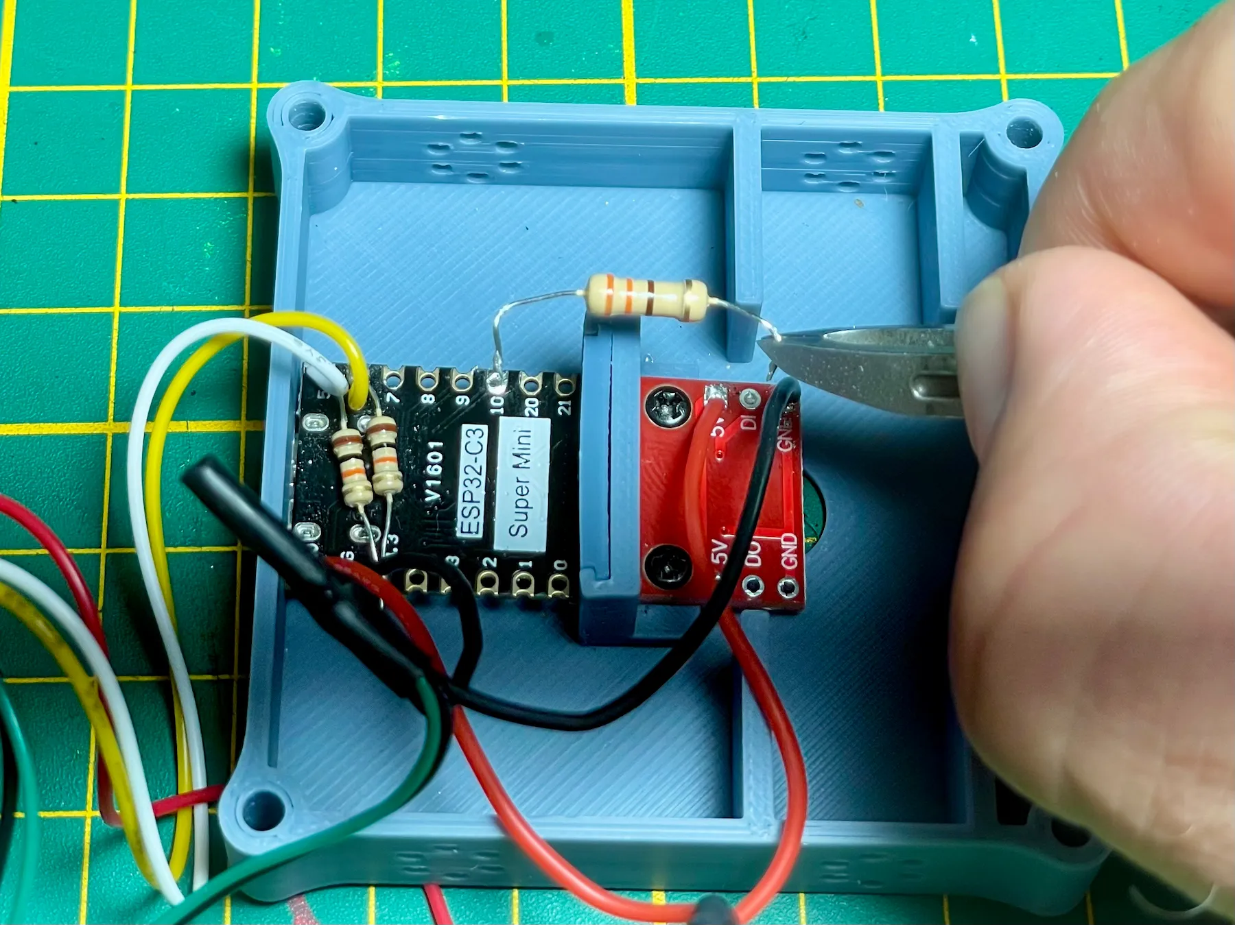
Finally, install the 330 Ω resistor between the ESP32 and the WS2812 data line. Fold the resistor neatly around the divider wall and trim the leads so it can be soldered directly into place.
Final assembly
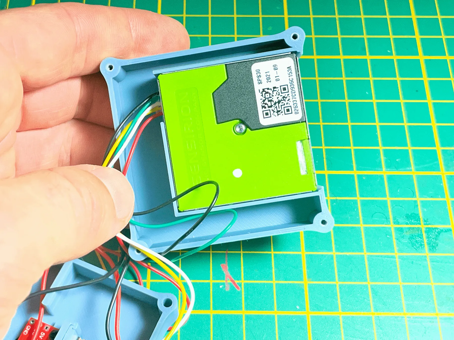
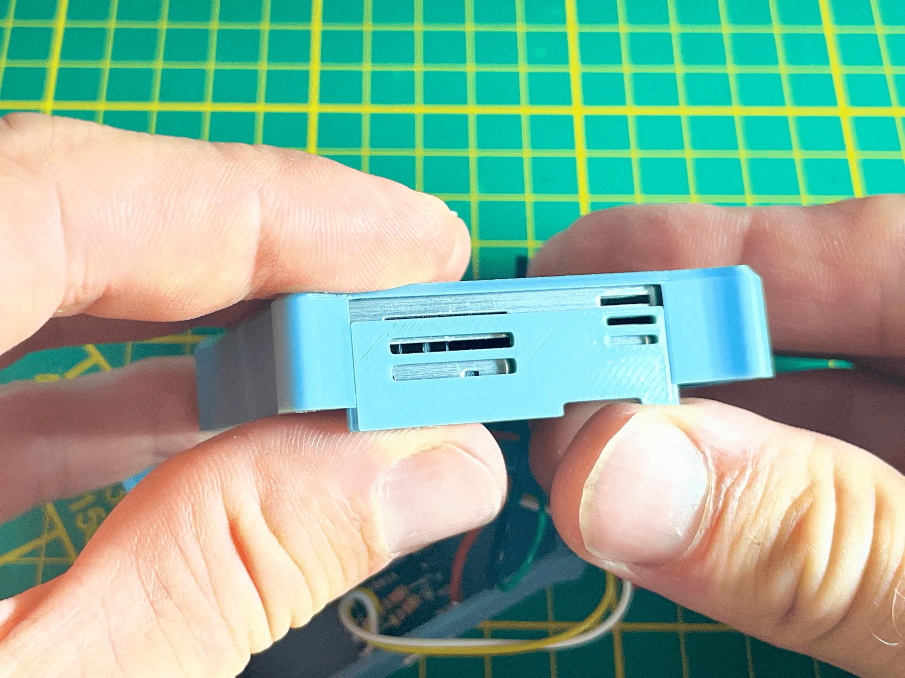
Connect the connector cables to the SPS30 and place the SPS30 into the upper housing. Then slide the air vent into position.
Firmware
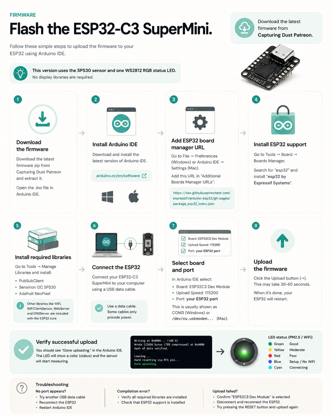
Upload the BREEZ firmware after soldering, before the ESP32 becomes harder to reach inside the housing.
The firmware package and 3D print files are available through Capturing Dust Patreon. The full visual flashing guide is linked here so this page can stay clean and focused.
First startup
After flashing, power the sensor.
The sensor immediately creates its own Wi-Fi setup network:
BREEZ_SETUP-XXXX
Connect your phone or computer to this network and open:
http://192.168.4.1
The setup page allows you to:
After saving your Wi-Fi credentials, the sensor automatically restarts and connects to your wireless network.
Once an internet connection is available, the sensor registers itself with the BREEZ platform.
The Claim Code shown on the setup page can then be used to add the sensor to your BREEZ account.
Further assembly
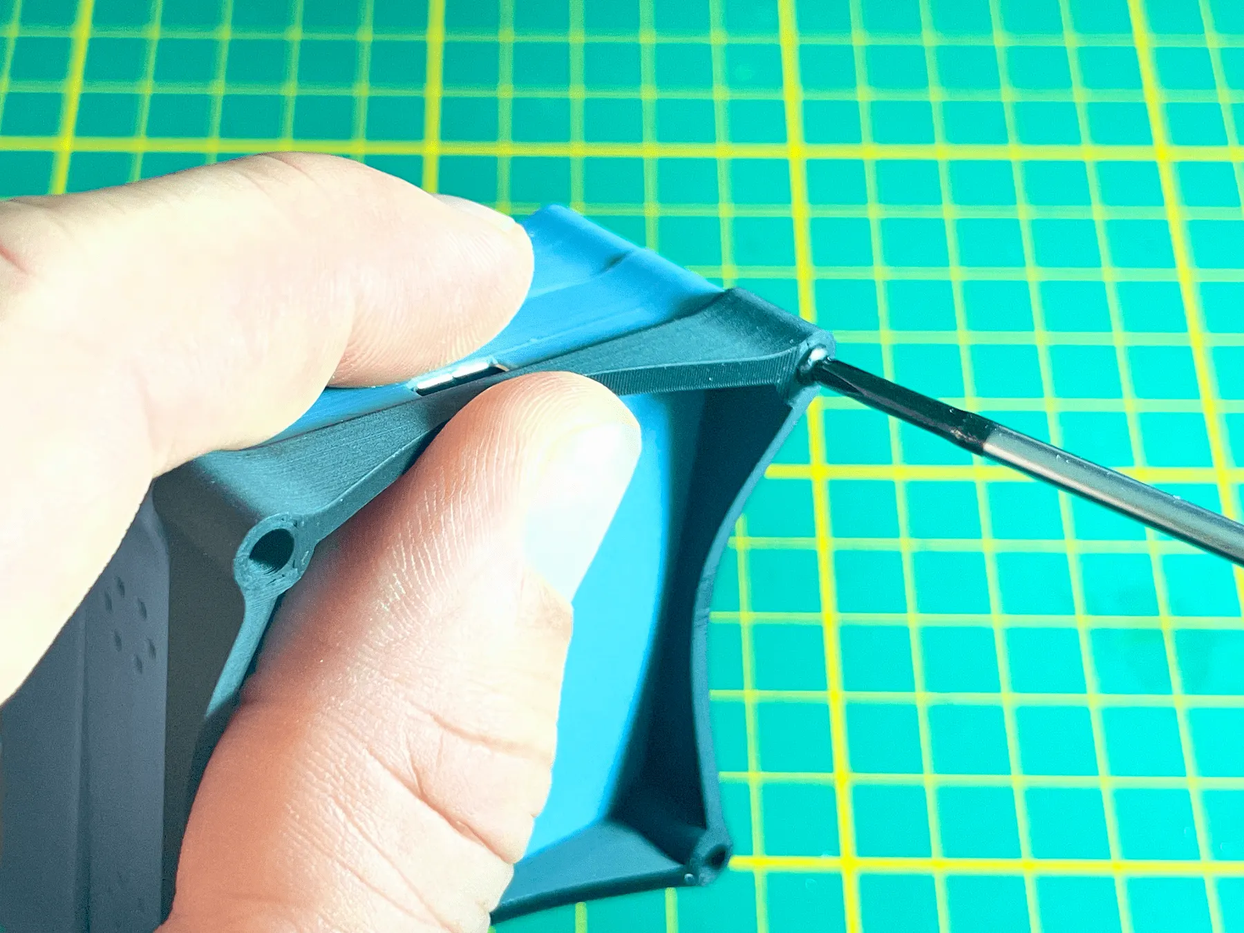
While closing the enclosure, carefully guide all wiring into the available space. None of the wires should become pinched or stretched.
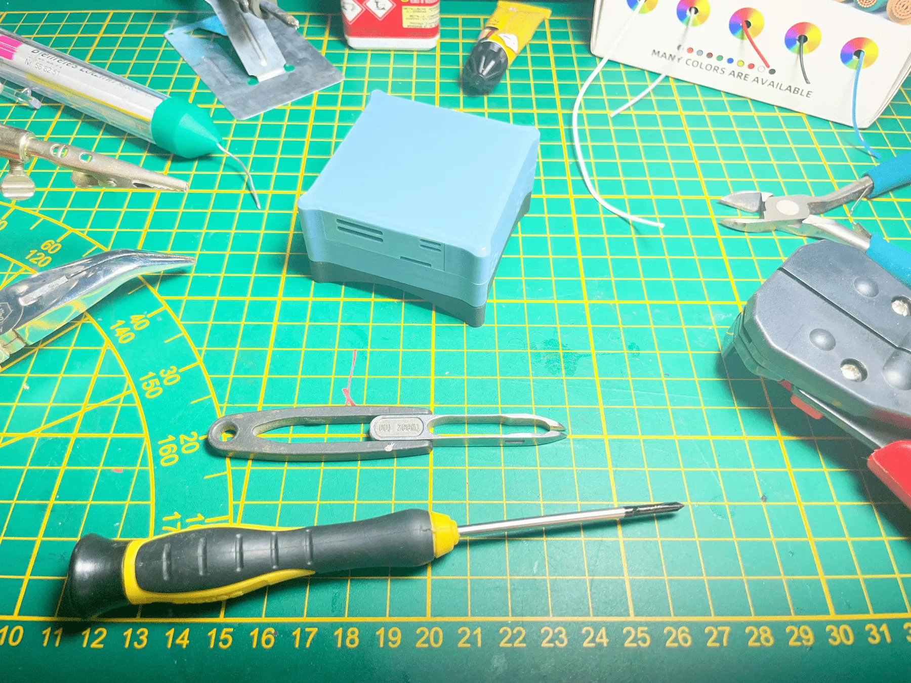
A small screwdriver can help gently push wires into place before tightening the screws.
Slide the sensor front plate into place. Attach the three layers of the casing using the remaining long screws.
Take your time and keep every wire clear of the screw posts and housing edges.
You’ve finished building your BREEZ dust sensor.
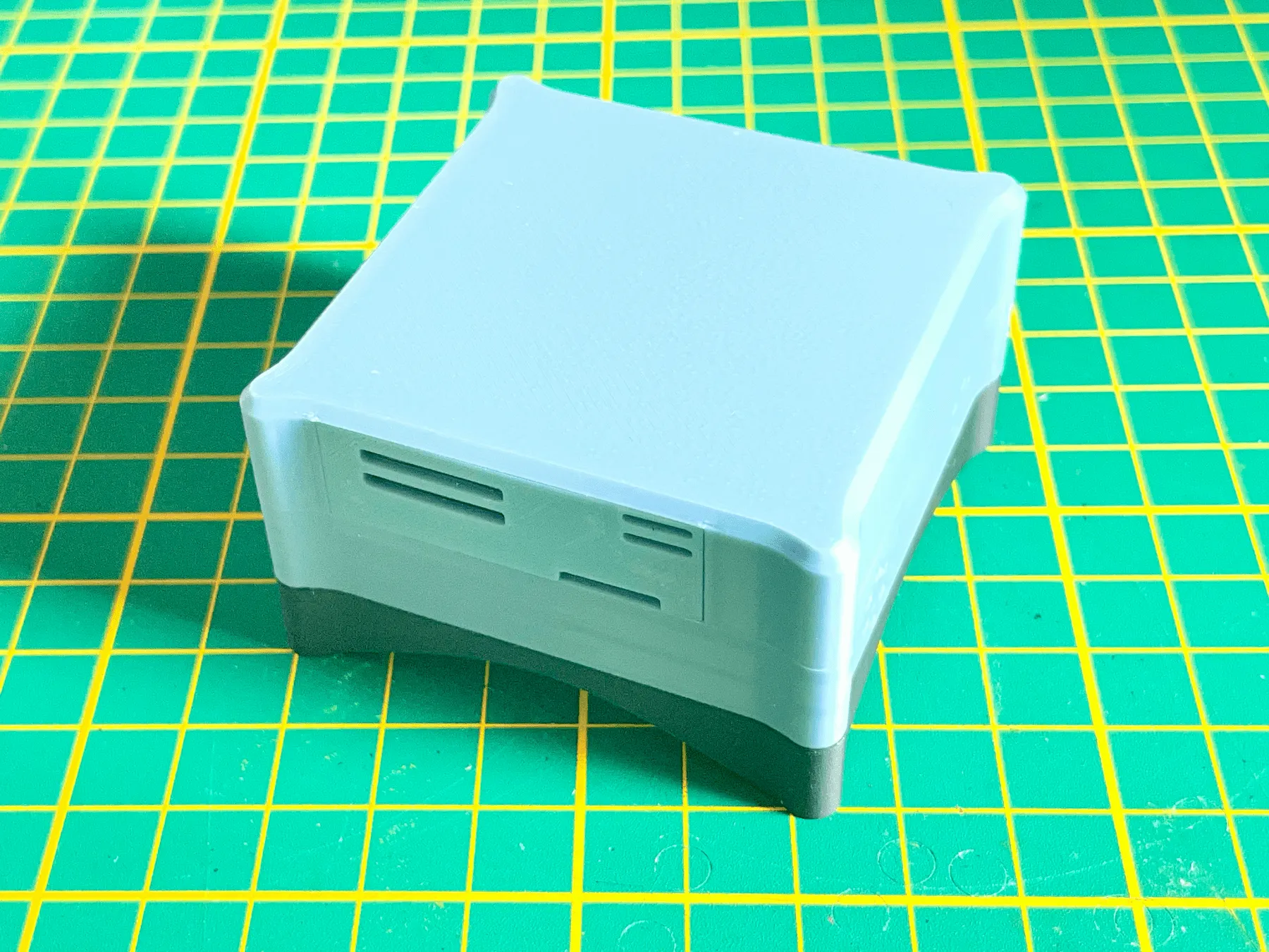
You’re ready
You built a fully operational particulate matter sensor that can monitor your workshop locally or connect to the BREEZ platform for live monitoring and long-term insights.
Now see what your lungs feel.
Open for makers
The BREEZ hardware is intentionally open for makers.
You're free to develop your own firmware, modify the hardware or use the sensor independently of the BREEZ platform for personal, non-commercial projects.
Got questions? Read our FAQ for quick help, or join the Capturing Dust Patreon community for priority support.